background image

Forma

 Model 700 Series _______________________________________________Safety

vi

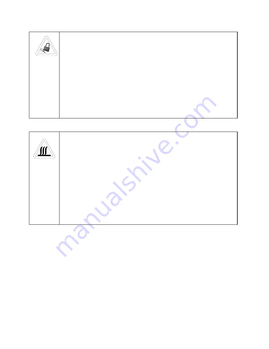
   Equipment being maintained or serviced must be turned off and locked off to prevent

possible injury.

   Risques potentiels liés à l’énergie. L’équipement en entretien ou en maintenance doit

être éteint et mis sous clé pour éviter des blessures possibles.

   Geräte, an denen Wartungs- oder Servicearbeiten durchgeführt werden, müssen

abgeschaltet und abgeschlossen werden, um Verletzungen zu vermeiden.

   El equipo recibiendo servicio o mantenimiento debe ser apagado y segurado para

prevenir danos.

   Hot surface(s) present which may cause burns to unprotected skin or to materials

which may be damaged by elevated temperatures

   Présence de surface(s) chaude(s) pouvant causer des brûlures sur la peau non

protégée, ou sur des matières pouvant être endommagées par des températures

élevées.

   Heiße Oberfläche(n) können ungeschützter Haut Verbrennungen zufügen oder

Schäden an Materialien verursachen, die nicht hitzebeständig sind.

   Superficias calientes que pueden causar quemaduras a piel sin proteccion o a

materiales que pueden estar danados por elevadas temperaturas.

√√

 Always use the proper protective equipment (clothing, gloves, goggles etc.).

√√

 Always dissipate extreme cold or heat and wear protective clothing.

√√

 Always follow good hygiene practices.

√√

 Each individual is responsible for his or her own safety.

Summary of Contents for 707

Page 1: ...e Chest Freezers 3 0 and 6 7 cu ft capacity Manual No 7000707 Rev 3 Read this Instruction Manual Failure to read understand and follow the instructions in this manual may result in damage to the unit injury to operating personnel and poor equipment performance CAUTION All internal adjustments and maintenance must be performed by qualified service personnel Refer to the serial tag on the back cover...

Page 2: ... manual In no event shall Forma Scientific Inc be held liable for any damages direct or incidental arising out of or related to the use of this manual MANUAL NO 7000707 3 19279 FR 1402 6 21 00 Revised electrical schematics aks 2 FR 1357 12 1 99 Updated per A Thomas for IEC 1010 CE listing ccs 18249 SI 7545 7 7 99 Added P N 195518 195519 air filter kits to parts list ccp 1 18286 FR 1296 5 11 99 Upd...

Page 3: ...ervice We can also provide you with a quotation on our Extended Warranty for your Forma products Whatever Forma products you need or use we will be happy to discuss your applications If you are experiencing technical problems working together we will help you locate the problem and chances are correct it yourself over the telephone without a service call When more extensive service is necessary we...

Page 4: ...n Sie den nachfolgenden Text sorgfältig Importante instruccions de operacion y o mantenimiento Lea el texto acompanante cuidadosamente Potential electrical hazards Only qualified persons should perform procedures associated with this symbol Ce symbole attire l attention de l utilisateur sur des risques électriques potentiels Seules des personnes qualifiées doivent appliquer les instructions et les...

Page 5: ... present which may cause burns to unprotected skin or to materials which may be damaged by elevated temperatures Présence de surface s chaude s pouvant causer des brûlures sur la peau non protégée ou sur des matières pouvant être endommagées par des températures élevées Heiße Oberfläche n können ungeschützter Haut Verbrennungen zufügen oder Schäden an Materialien verursachen die nicht hitzebeständ...

Page 6: ...Connecting recorder battery 1 7 b Installing the chart paper 1 7 1 9 Attaching the Power Cord 1 8 1 10 Power Switch mains disconnect 1 8 1 11 Electrical Requirements and Connection 1 9 1 12 Factory Settings 1 9 1 13 Start Up and Loading 1 9 Section 2 Operation 2 1 Changing the Control Temperature Set Point 2 1 2 2 Changing the Over Temperature Alarm Set Point 2 1 2 3 Alarms 2 2 2 4 Silencing the O...

Page 7: ...lter 4 1 4 3 Cleaning the Condenser 4 1 4 4 Defrosting the Chamber 4 2 4 5 Cleaning the Lid Gasket 4 2 4 6 Replacing the Battery 4 3 4 7 Preparing the Unit for Storage 4 3 Section 5 Service 5 1 Servicing the Refrigeration System 5 1 Section 6 Specifications Section 7 Parts List Section 8 Refrigeration Drawings Section 9 Electrical Schematics Section 10 Warranty Information ...

Page 8: ...ed end over the ramp brackets on the pallet The support blocks on the ramps will be facing down Before moving the freezer make sure the casters are unlocked and moving freely Align the caster with the ramp boards Use adequate personnel to roll the freezer off the pallet If tipped more than 45 allow the unit to set upright for 24 hours before start up The freezer can be easily pushed to the desired...

Page 9: ...ailure or high ambient temperature Set Point Adjustment Screw Sets the control temperature set point Normal Standby switch Silences the audible alarm Low Battery indicator Flashes when the battery needs to be replaced Over Temp indicator Flashes when the chamber temperature rises above the Over Temperature Alarm setting Voltage Compensation indicator Indicates when the in coming electrical power i...

Page 10: ...__Installation Start Up 1 3 1 2 3 1 2 3 Figure 1 2 Figure 1 3 3 0 cu ft Chest Freezer 6 7 cu ft Chest Freezer Figure 1 4 Chest Freezer Base back view Figure 1 5 Chamber Probe Assembly Recorder Probe Probe Cover Performance Alarm Monitor and Temperature Probe ...

Page 11: ...tions supplied from a supply comparable to public mains such as hospital and research laboratories and most industrial laboratories the expected transient overvoltage is 2500V for a 230V supply and 1500V for a 120V supply 2 Pollution degree describes the amount of conductive pollution present in the operating environment Pollution degree 2 assumes that normally only non conductive pollution such a...

Page 12: ...y remove the grill on the front of the freezer The grill is attached to the freezer by friction plugs on each of the four corners and is readily pulled off The battery is the rectangle fastened by Velcro to the compressor compartment frame and has a connector with red and black wires Another red and black wire set with connector is secured to the wiring harness passing through the area of the free...

Page 13: ... the glass door of the recorder and connect the 9 volt battery The green light on the recorder will come on b Installing the chart paper 1 Open the glass door of the recorder and press button 3 until the pen begins to move outward 2 Unscrew the knob at the center of the chart and remove the paper 3 Install the new chart paper position the paper to the correct time line and replace the knob 4 Remov...

Page 14: ...e Check voltage rating on the serial tag of the unit and compare it with the outlet voltage With the power switch turned off plug the line cord into the wall outlet 1 12 Factory Settings Control Temperature 707 771 80 C 733 754 75 C Over Temperature Alarm 65 C If you wish to change any of these settings see the appropriate section s in Section 2 1 13 Start Up and Loading Turn the freezer on and al...

Page 15: ...ing range Setting the unit below this range will cause the compressors to operate continuously and reduce compressor life 2 2 Changing the Over Temp Alarm Set Point The following procedure sets the alarm for a precise temperature during initial set up If a precise temperature is not required set R9 to the desired temperature 1 Set the unit to operate at the desired alarm point see Section 2 1 and ...

Page 16: ... Description Visual Audible Cause Action Required Over Temperature Flashing red On Unit is above alarm setpoint Addition of excessive product load Check freezer operation Condenser Hot On red Filter and or condenser dirty Operating freezer in greater than 40 C ambient See Section 4 2 and 4 3 for cleaning filter and condenser Low Battery Flashing red Rechargeable battery not connected Rechargeable ...

Page 17: ...arm Move the switch from the NORMAL position to the STANDBY position When the alarm condition has been corrected the alarm will sound The switch must then be returned to the NORMAL position to exit STANDBY mode If the unit is left in the STANDBY mode none of the alarms listed will sound alarm lights only will turn on ...

Page 18: ...operating temperature 2 Remove the top two screws securing the control panel and loosen the bottom screws 3 Carefully remove the control panel 4 Remove the six screws securing the cover of box attached to the inside of the control panel Remove the cover 5 Adjust R17 until the control panel display matches the independent measuring device Several turns of R17 may be required to achieve the desired ...

Page 19: ...egin to flash Count the number of flashes to determine the present program setting 4 To change the program setting press the left or right arrows to increase or decrease the count 5 When the desired program number is flashing press button 3 to bring the pen arm back onto the chart Recording will begin in the new program NOTE Changing ranges may require an offset calibration as outlined in Section ...

Page 20: ... Figure 1 5 3 After about three minutes compare the thermometer reading with the chart recorder reading 4 If an adjustment is necessary press the 1 button to move the pen to the left or the 2 to move the pen to the right The button must be held about five seconds before the pen begins to move Release the button when the pen position matches the thermometer NOTE The felt tip pen on the recorder req...

Page 21: ...attach the grille Depending upon environmental conditions the filter may need to be cleaned or replaced more frequently If the filter becomes torn or excessively dirty a replacement can be purchased from Forma Scientific See the Parts List Section 7 for filter part number A filter kit set of 5 filters is also available 4 3 Cleaning the Condenser minimum of twice a year 1 Locate the grille on the r...

Page 22: ... soft cloth 8 Plug unit in and turn power switch on 9 Allow the freezer to operate empty overnight before reloading the product 4 5 Cleaning the Lid Gasket minimum monthly 1 Using a soft cloth remove any frost build up from the gasket sub lids and lid The lid gasket may need to be cleaned more frequently if dirt or excessive frost build up prevents the door from closing properly 4 6 Replacing the ...

Page 23: ...lcro to the compressor compartment frame and has a connector with red and black wires Another red and black wire set with connector is secured to the wiring harness passing through this area of the freezer 3 Disconnect the two wire connectors replace the battery pack and secure with the Velcro 4 Reconnect the battery and replace the grill 5 Plug unit in and turn power switch on 4 7 Preparing the U...

Page 24: ...ible Cause No Temperature Display Power line cord disconnected or not properly installed External power circuit breaker tripped open Main power switch OFF 24V transformer fuses open Chamber Temperature Deviates from Setpoint Too much warm product added Lid open too long Inadequate air circulation Unit is out of calibration Dirty condenser High ambient temperature Too Much Frost Build Up Lid not pr...

Page 25: ...ty 3 0 cu ft 85 liters Insulation Type Non CFC urethane Sides 5 0 12 70cm Lid 2 0 5 08cm Sub Lid 1 0 2 54cm Electrical 733 120 VAC 1PH 60 Hz 10 0 FLA Operating Range 108VAC 130VAC 754 230 VAC 1 PH 50 Hz 8 0 FLA Operating Range 208VAC 240VAC Breaker Requirements Dedicated Circuit 733 15 Amp 120V 754 15 Amp 230V Automatic Voltage Compensator 733 Low Cut in 110V Cut out 115V Volts Boost 10 High Cut i...

Page 26: ... Capacity 6 7 Cu Ft 190 liters Insulation Type Non CFC urethane Sides 5 12 7 cm Lid 2 5 08 cm Sub Lid 1 2 54 cm Electrical 707 120 VAC 1PH 60 Hz 14 FLA Operating Range 108VAC 130VAC 771 230 VAC 1 PH 50 Hz 8 FLA Operating Range 208VAC 240VAC Breaker Requirements Dedicated Circuit 707 20 Amp 120V 771 15 Amp 230V Automatic Voltage Compensator Low Cut in 110V Cut out 115V Volts Boost 10 Cut in 210V Cu...

Page 27: ...yer 1 4 ODS 250111 1 Solenoid Valve 120V 207010 1 Pressure Switch Cutout high pressure cut out 350 PSIG 900113 1 Tubeaxial Fan 120V 760198 1 Air Filter 11 4 x 14 4 230110 2 1 0 Amp Fuse Slo Blow Transformer 420101 1 Transformer 25 VA 24Volt 1990150 1 Low Stage Compressor with Zerol 150T 120V 1 4 HP Models 733 754 2990150 1 High Stage Compressor with Ester Oil 120V 1 4 HP Models 733 754 970023 70 c...

Page 28: ...t 350 PSIG 900113 2 Tubeaxial Fan 120V Model 707 900111 2 Tubeaxial Fan 230V Model 771 760165 1 Air Filter 11 4 x 25 9 195519 1 5 760165 Air Filters 230110 2 1 0 Amp Fuse Slo Blow Transformer 420101 1 Transformer 25 VA 24Volt 1990209 1 Low Stage Compressor with Zerol 150T 230V 1 3 HP Model 771 2990209 1 High Stage Compressor with Ester Oil 230V 1 3 HP Model 771 1203017 1 Low Stage Compressor with ...

Page 29: ...Forma Model 700 Series _________________________________Refrigeration Drawings 8 1 Section 8 Refrigeration Drawings ...

Page 30: ......

Page 31: ......

Page 32: ......

Page 33: ...Forma Model 700 Series ___________________________________Electrical Schematics 9 1 Section 9 Electrical Schematics ...

Page 34: ......

Page 35: ......

Page 36: ......

Page 37: ......

Page 38: ......

Page 39: ......

Page 40: ......

Page 41: ......

Page 42: ......

Page 43: ......

Page 44: ......

Page 45: ......

Reviews: