background image

Master Section Overview

Main and Zone outputs are available in stereo, along with a separate mono output. All these
outputs are balanced on XLR connectors. Booth monitors output is available in stereo or
switchable to mono and again these outputs are balanced on XLR connectors.

A recording output is provided on gold plated phono sockets.

There are 3 insert loops provided. 1 & 2 are selected via the X-fade assign buttons and feature
latching and punch selector buttons along with wet / dry mixing control and gain trims. Mono and
cue switches are fitted to both sections. There is also an illuminated loop swap button that allows
the connected effects processors to be swapped over to the other channel.

The third effects loop is connected to the main output chain. This is selected by an illuminated
push button.

All effects loop connectors are pairs of 3 pole jacks, each socket providing send and return
paths.

Visual metering is by 2 twin 12 segment led VU meters; one for cue signals and one for output
signals.

Comprehensive headphones monitoring is provided featuring a powerful stereo headphones
amplifier.
6.5mm and 3.5mm stereo jacks are provided.
A split cue switch and monitor balance control are fitted.

The Console Microphone channel is located above the phones section and features two band
equalisation, volume control, illuminated on-off switch and cue button.

Dimensions   (Exc. Knobs & connectors):

Width 483mm  (19”)    Height 312mm (12.25"-7RU)   Depth 110mm (4.33")

Power Supply

The Mixer has a fully regulated internal power supply that is designed to operate on
220-240Vac or 110-120Vac. Selection is by an internal switch that is accessed by removing the
fader panel.

DAMAGE MAY RESULT IF THE UNIT IS CONNECTED TO THE WRONG
SUPPLY VOLTAGE.

Fuses
Mains fuse sizes are 800mA anti-surge for 220-240Vac and 1.5A anti-surge for 110-120Vac
operation.

It is important for safety reasons that the correct fuse sizes are always
used.

2

Summary of Contents for FF - 6000

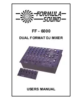
Page 1: ...FF 6000 DUAL FORMAT DJ MIXER USERS MANUAL...

Page 2: ...wer is available for microphones internal selection Channels 3 to 6 are switchable between a stereo line input and a phono RIAA or line input Phono line selection is via a concealed push switch access...

Page 3: ...jacks each socket providing send and return paths Visual metering is by 2 twin 12 segment led VU meters one for cue signals and one for output signals Comprehensive headphones monitoring is provided f...

Page 4: ...l is just below clipping If lit it means that the gain is set too high 3 Band equalisation provides 5dB boost and 23dB cut HF 10kHz MID 1kHz BASS 100Hz The centre detent denotes the flat position X Fa...

Page 5: ...pensate for differences in track levels Clip indicator This is a red l e d that indicates when the channel signal is just below clipping If lit it means that the gain is set too high 3 Band equalisati...

Page 6: ...its cue button depressed or the sum of channels if more than one is selected If no cue buttons are depressed the meter reads the main output level which is dependent on the MASTER control setting Tur...

Page 7: ...ith the control set to fully Dry no effect is added With the control set to fully Wet just the effect return is added to the mix and the original signal is removed Momentary punch and latching switche...

Page 8: ...NPUT TRIM PRESETS INSTALLATION CONNECTIONS AND GOOD WIRING PRACTICE The installation of professional audio systems should be left to experienced engineers wherever possible The interconnection of audi...

Page 9: ...t quality at every stage of manufacture This attention to detail has helped to win us 14 industry awards to date and has earned us a world wide reputation for the high quality and reliability of our p...

Page 10: ...eo inputs rear trim min 0dB 20dB Microphone input max 75db Microphone input min 0dB Maximum input level Stereo input A line 20dBV Stereo input A RIAA 8dBV 400mV Stereo input B 20dBV Microphone 4 dBV I...

Reviews: