background image

PFL

MUTE

E.Q. OUT

BASS

MID

TREBLE

1L

GAIN

1M

Page 2

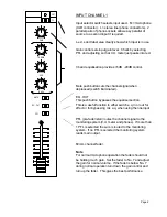
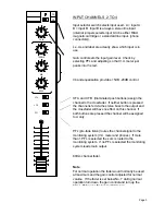
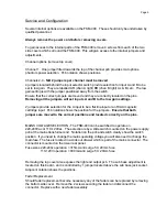
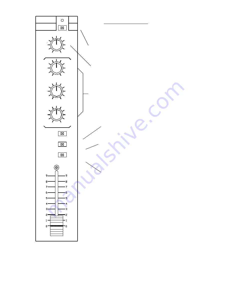
INPUT CHANNEL 1

Input selector switch selects input used.  M = microphone
(XLR connector).  L = stereo line (phono connectors).  2
parallel pairs of phono sockets allow easy parallel of
source to a second input if required.

L.e.d.s and label area clearly show which input is in use.

Gain control sets input gain level.  Check by selecting
PFL and adjusting so that V.U. meter just peaks into red.

3 band equalisation pr5dB  -20dB control.

Mute push button cuts the channel signal when
depressed (switch illuminated).

E.Q. OUT
This push button bypasses the equaliser section.
This is a useful function to either switch e.q. in or out for
effect or for bypassing mic e.q. when using the line input.

PFL (pre-fade listen) routes the channel signal to the
monitoring system (V.U. meter and phones).  If more than
1 PFL is selected the sum is routed to the monitoring
system.  If no PFL is selected the monitoring system
reads main output.

60mm channel fader.

Note

For normal microphone operation the fader should not
be holding much gain.  Set the fader to No. 7 and adjust
the gain for normal volume.  If the fader is below No. 7
during normal operation turn down the gain control and
turn up the fader.  This gives the best performance.

Summary of Contents for FSM-400

Page 1: ...FSM 400 PRODUCTION MIXER USERS MANUAL...

Page 2: ...output section provides plenty of facilities to cope with most applications It includes a new design of crossfade circuitry that places less demand on the fader to ensure exemplary attenuation and ex...

Page 3: ...epressed switch illuminated E Q OUT This push button bypasses the equaliser section This is a useful function to either switch e q in or out for effect or for bypassing mic e q when using the line inp...

Page 4: ...assign the channel to the crossfader If neither button is pressed the channel is fed via the stereo buss to the output and the crossfader will have no effect on this channel If both buttons are presse...

Page 5: ...ls The changeover is by selecting PFL on any channel Any number of PFL sources may be selected and the sum of these will be monitored This provides a very versatile monitoring facility Depressing the...

Page 6: ...ction is click free and provides the creative operator with a useful facility ZONE controls a further output similar to the master output but without the balanced output driver Stereo or mono outputs...

Page 7: ...A input to be a flat line input or an RIAA magnetic cartridge input Pcb notation shows the position for the jumpers Ensure that both jumpers are moved to the correct positions and located correctly o...

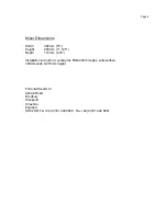
Page 8: ...t 283mm 11 125 Depth 110mm 4 33 Installation cut out for mounting the FSM 400 through a work surface 330mm wide X 270mm height Formula Sound Ltd Ashton Road Bredbury Stockport Cheshire England SK6 2SR...

Page 9: ...sed by incorrect system grounding When several items of audio equipment are connected together with unbalanced connections i e 2 connections single screened cable etc the signal common connection is t...

Page 10: ...Page 8...

Reviews: