4-11
FORMULA
CONTROLS AND INDICATORS
SUN SPORT
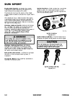
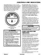
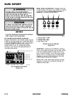
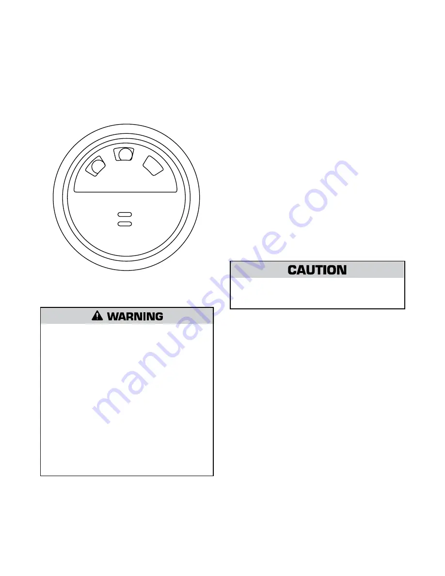
Fume Detector Gauge
—Monitors the engine
compartment for excessive fuel fumes. The gauge
is mounted at the helm and a sensor is located in
the bilge area where fumes collect. The system
also monitors for unburned hydrocarbons from a
faulty exhaust system and hydrogen battery
vapors. Refer to the fume detector owner’s
manual for additional information.
The fume detector
s
y
s
tem
s
hould be
con
s
idered a
s
upplemental warning
s
y
s
tem. It i
s
not meant to replace
s
tandard
s
afety practice
s
which
s
hould be followed
around explo
s
ive ga
s
e
s
.
If the fume detector indicate
s
a dangerou
s
condition, do the following:
l
Do not operate electrical equipment.
l
Extingui
s
h open flame
s
and
s
moking
material
s
immediately.
l
Turn OFF the engine
s
and generator.
l
Wait five minute
s
before opening the
engine compartment to inve
s
tigate the
cau
s
e.
l
Determine the cau
s
e and correct it
immediately before re
s
uming operation.
Fume Detector Gauge
Figure 4-29
GASOLINE FUME DETECTOR
MUTE
TEST
M - 1
Bilge High Water Alarm
—Alerts operator of
excessive water in the bilge. Sounding of the
alarm may be an indication of a) problems with
the automatic bilge pump system, or b) an
intrusion of water which exceeds the bilge pump
system’s removal capabilities. A sensor mounted
in the engine compartment activates the alarm,
which manifests itself as a shrill wavering siren.
The alarm has a built-in 10-second delay, which is
designed to eliminate nuisance tripping (i.e., the
alarm will not sound unless the sensor is activated
continuously for 10 seconds or greater). The
alarm will stop once the excessive water is
cleared. Refer to
Bilge and Blower System
in
Section 5
.
Engine Alarm
—Sounds an alarm when an
engine temperature exceeds the set limit or if the
oil pressure drops below the set range. If the
alarm sounds during operation, immediately turn
OFF the engine and determine the cause. The
engine alarm will also sound if the outdrive lube
level falls to a critical level. Consult the propulsion
unit owner’s manual in your Owner Information
Binder for additional information.
Continued operation of an engine after the
warning alarm ha
s
s
ounded may cau
s
e
s
evere engine damage.
CABIN CONTROLS AND
INDICATORS
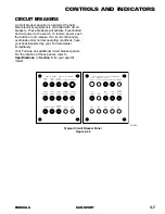
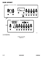
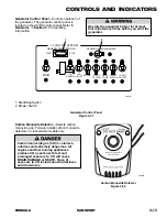
AC/DC Control Panel
—This panel controls the
distribution of the 110-volt alternating current
(VAC) electrical system and the 12-volt direct
current (VDC) electrical system.
Both the AC and DC circuits are controlled by
switch-type circuit breakers. The circuit breakers
serve two functions: 1) They allow you to
manually enable or disable a circuit by moving the
switch ON or OFF, and 2) they protect the system
by automatically opening the circuit if a short or
overloaded condition occurs.
Check the circuit if a particular piece of equipment
stops working. A tripped circuit breaker indicates
the circuit is overloaded. You should determine
and correct the cause of a problem before
resetting a circuit breaker.
Reset the breaker by pressing it back into place.
Contact your Formula dealer if a circuit beaker
trips repeatedly.
Refer to
Section 5
for operation of the 12-VDC
and 110-VAC electrical systems.
FOR012
Summary of Contents for SUN SPORT
Page 20: ...2 12 FORMULA SUN SPORT SUN SPORT...
Page 22: ...3 2 FORMULA SUN SPORT SUN SPORT DIMENSIONS FOR218A F E C B D A FOR218A...
Page 42: ...3 22 FORMULA SUN SPORT SUN SPORT...
Page 120: ...9 8 FORMULA SUN SPORT SUN SPORT...
Page 124: ...10 4 FORMULA SUN SPORT SUN SPORT...
Page 128: ...11 4 FORMULA SUN SPORT SUN SPORT...
Page 132: ...12 4 FORMULA SUN SPORT SUN SPORT...
Page 134: ...13 2 FORMULA SUN SPORT SUN SPORT FUEL LOG Date Gallons Date Gallons Date Gallons Date Gallons...
Page 138: ...13 6 FORMULA SUN SPORT SUN SPORT...

