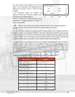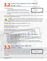
Regardless of the number of channels being used, both channels must be set to
an equal Self-Check Cycle Time. If different self-check cycle times are set, the
shorter of the two settings will be effective on both Channels.
If one channel fails at any time, for any reason, the other channel will continue to
operate.
same time.
NOTICE:
NOTICE:
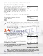
SAVING CONFIGURATION
3.4
F1 F2 F3 F4
F1 F2 F3 F4
F1 F2 F3 F4
F1 F2 F3 F4
F1 F2 F3 F4
Valid Range:
30 - 600
> 0<
OK
Self Check
Delay = 300
Seconds
CHG NXT
RESTORE OR SAVE
860 PPS UV
LOAD SAVE SELF
OLD NEW CHK
PPS CHK FAIL
PPS CHK FAIL
PPS CHK FAIL
860 PPS UV
Set 0
372001-02 Rev L
39
Summary of Contents for 408100-00
Page 4: ...372001 02 Rev Kv TABLE OF CONTENTS ...
Page 9: ...372001 02 Rev L 2 output This pulse train then serves as the input to the microprocessor ...
Page 10: ...372001 02 Rev L 3 Figure 1 1 IDD 9000 Block Diagram ...
Page 15: ...372001 02 Rev L 8 Figure 2 1 PM IDD 9000 External Connectors ...
Page 20: ...Upgrading from a PM DR6101E CAUTION 372001 02 Rev L 13 ...
Page 28: ...Figure 2 3 Typical Installation with Sealtight Fitted 372001 02 Rev L 21 ...
Page 29: ...Figure 2 4 IDD Detector Head Wiring 372001 02 Rev L 22 CONNECTING IDD DETECTOR HEADS 2 5 1 ...
Page 37: ...COM DSP KBD COM DSP KBD 372001 02 Rev L 30 ...
Page 39: ...NOTICE NOTICE MODE 3 1 IDD Channel Tuning IDD Gain 3 1 1 3 1 1 1 372001 02 Rev L 32 ...
Page 49: ...STORAGE AND HANDLING REQUIREMENTS 4 3 372001 02 Rev L 42 ...
Page 50: ...SECTION 5 RMA WARRANTY 372001 02 Rev L 43 ...
Page 51: ...SECTION 6 SPARE PARTS Email Phone Fax 372001 02 Rev L 44 372001 02 Rev L 44 ...


