background image

19

Ignition

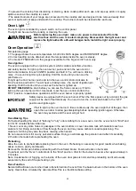
To light up the cooktop burners, push and turn the appropriate control knob counter
clockwise to “Hi” position. You will hear a clicking noise – the sound of ignition pin
sparking.
Once burner ignition has been achieved, turn the burner control knob to adjust desired
flame size. If the knob stays at “Hi”, it will continue clicking.

Heat Settings:
Hi

Ignites the burners.

Simmer

Melting small quantities, steaming rice, warming food, melting chocolate or butter.

Low

Melting large quantities.

Low-Medium

Low-temperature frying, simmering large quantities, heating milk, cream sauces,
gravies.

Medium

Sauteing and browning, braising, pan-frying, maintaining slow boil on large quantities.

Medium-Hi

High-temperature frying, pan boiling, maintaining slow boil on large quantities.

Hi

Boiling liquid quickly, deep frying.

CAUTION

Never leave pans on a high setting unattended. Be careful when cooking food in
fat or grease; it can become hot enough to ignite. Burner flames not covered by
cookware present a risk of fire or clothing ignition. Never let flames extend beyond
the sides of the cookware. Failure to comply may result in serious injury.

Simmer and Boil

A smaller flame will give the best results when simmering. Small flames offer precise cooking performance for
delicate foods, keeping food warm, melting chocolate or butter, and for cooking over low heat for long period of
time.
The highest (larger) flame settings provide the maximum heat that is available on your range. This setting should
be used for heavy cooking jobs such as boiling water and cooking pasts.

Flame Size

• When you adjust the flame size, watch the flame when you turn the knob.
• Any flame exceeding the bottom of the cookware will not heat faster and may be
hazardous .
• The flame should be steady and blue in color. Impurity in the gas supply may cause
an orange flame during initial operation.

Power Failure

• If the gas does not ignite within 4 seconds, turn off the valve and allow at least five minutes for any gas to
dissipate. Repeat the lighting procedure.
• In the event of a power failure, the surface burners can be lighted manually. Hold a lighted match near a burner
and turn the knob counter-clockwise to “HI”. After burner lights, turn knob to the desired setting.

Burner Grills

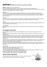
1. The grills must be properly positioned before cooking. Improper installation of the grills may result in scratching
of the cooktop and / or poor combustion.
2. Do not operate the burners without a pan or utensil on the grills.

Griddle Operation (Only available on the 48”models)

Before Using the Griddle
1. Clean the griddle thoroughly with warm, soapy water to remove dust or any protective coating.
2. Rinse with clean water and wipe off to dry with soft, clean, lint-free towel/cloth.
Use of Griddle
1.Place the griddle to the position you need to cook.
2. Preheat the griddle for 10-12 minutes.
3. Butter or cooking oil can be added for more flavor, then place the food to cook.

CAUTION

The surface of the grill is hot after use. Please allow sufficient time for the grill to
cool before cleaning.

Cooptop cleaning tips

Summary of Contents for Alta Qualita FFSGS6291-30

Page 1: ...RANGE 5015011 Conforms to ANSI STD Z21 1 2018 Certified to CSA STD 1 1 2018 Household Cooking Gas Appliances INSTALLATION GUIDE SPECIFICATIONS INSTALLATION AND MORE MODEL NUMBERS FFSGS6291 30 FFSGS629...

Page 2: ...andle Installation 8 Surface Burner Grills Installation 8 Oven Rack Installation 9 Electrical 9 Gas Supply 10 Product Dimensions and Cabinets 11 Exhaust Hood Installation 12 Gas Conversion Operation 1...

Page 3: ...e Address Phone Save time and money Before you call for service check the Troubleshooting Guide It lists the causes of minor operating problems that you can correct yourself SERVICE IN CANADA Keep the...

Page 4: ...gasoline or other flammable vapors and liquids in the vicinity of this or any other appliance WHAT TO DO IF YOU SMELL GAS Do not try to light any appliance Do not touch any electrical switch Do not us...

Page 5: ...o repair or replace any part of your range unless it is specifically recommended in this manual 4 Your range is shipped from the factory set for use with natural gas or propane LP gas It can be conver...

Page 6: ...the ventilator OFF in case of a fire or when intentionally flaming liquor or other spirits on the cooktop The blower if in operation could spread the flames WARNING KEEP FLAMMABLE MATERIAL AWAY FROM T...

Page 7: ...resulting in a gas leak and risk of fire Do not use aluminum foil to cover the grills or line any part of the cooktop Doing so may result in carbon monoxide poisoning overheating of the cooktop surfac...

Page 8: ...features are on all models Appearance may vary 1 Oven Vents 2 Surface Burner Grates 3 Griddle for FFSGS6291 48 only 4 Control panel 5 Oven light switch 6 Convection Fan switch 7 Oven broil burner cont...

Page 9: ...pieces Burner grill for FFSGS6291 48 only 1 piece Burner grill for FFSGS6291 30 only 1 piece Cook plate Griddle for FFSGS6291 48 only 1 piece Oven door handle 2pcs for FFSGS6291 48 1 piece Burner Cap...

Page 10: ...ion the handle holder correctly to accept the screw bolt on the outside of oven door screw the bolt half way into the handle holder Caution Do not tighten the bolt to the handle holder before the hand...

Page 11: ...ian Electrical Code Part 1 and or local codes The power supply must be the correct polarity Reverse polarity will result in continuous sparking of the electrodes even after flame ignition If there is...

Page 12: ...is the responsibility and obligation of the customer to have it replaced with a properly grounded three prong wall receptacle Do not cut or remove the grounding prong from the power cord Electric Pow...

Page 13: ...ust be equipped with an approved external gas shut off valve located near the range in an accessible location Do not block access to the shut off valve Refer to the illustration above A 3 4 19 ID gas...

Page 14: ...48 Model 48 1219mm Exhaust Hood Installation The bottom of the hood should be 30 min to 36 above the countertop This would typically result in the bottom of the hood being 66 to 72 above the floor The...

Page 15: ...to identify a factory trained professional near your home WARNING Before carrying out this operation disconnect the range from gas and electricity Fail to do so may result in fire or electrical shock...

Page 16: ...late and burner side guard plate back to place and put back the oven bottom cover STEP 2 Surface Burners 2 1 Remove cooking grates and burner caps 2 2 Lift off burner spreader 2 3 Remove the factory i...

Page 17: ...G 0 9 2 outer 0 46 1 center 9000BTU NG 1 33 LPG 0 93 15000BTU NG 1 75 LPG 1 18 9000BTU NG 1 33 LPG 0 93 9000BTU NG 1 33 LPG 0 93 15000BTU NG 1 75 LPG 1 18 15000BTU NG 1 75 LPG 1 18 15000BTU NG 1 75 LP...

Page 18: ...injector with the air shutter 3 4 Assemble the bracket back to place Repeat above steps for 18 oven for 48 ranges only Injector diameter for oven bottom burners Model FFSGS6291 30 FFSGS6291 36 FFSGS62...

Page 19: ...loosen the lock screw re position the air shutter and tighten the lock screw 5 4 Assemble the burners back to place 5 5 Retest the burner When the flame is a distinct blue color and burning steadily...

Page 20: ...check that all range controls are in the OFF position and turn on the main gas supply valve If a flexible metal connector is being used verify it is not kinked then attach the gas supply line to the...

Page 21: ...um heat that is available on your range This setting should be used for heavy cooking jobs such as boiling water and cooking pasts Flame Size When you adjust the flame size watch the flame when you tu...

Page 22: ...reset the oven control knob to the OFF position repeat above operations until the oven burner is properly ignited IMPORTANT Safety device is equipped with the oven burner When the flame goes out by a...

Page 23: ...pan and insert not included allow dripping grease to drain and be kept away from the high heat of the oven broiler DO NOT use the broil pan without the insert DO NOT cover the broil pan insert with f...

Page 24: ...ark Randomly Electrical plug is not connected properly with a live power outlet Gas supply not turned on Burner parts not replaced correctly Holes in the simmer rings or slits in the burner rings are...

Page 25: ...first few times the oven is used Condensation Or Fogging On The Glass of inside of Oven Door Condensation or fogging on the glass of inside of oven door is normal during the preheating of the oven and...

Page 26: ...24 WIRE DIAGRAM...

Page 27: ...25...

Page 28: ...26...

Reviews: