MICROpod User Manual
A0016-09-0001
Version Number: 4.00
Page 3
Template Version: 2.01
Revision Date: 24.06.2013
Forsberg Services Limited
Company Registration No: SC104949
Registered Office: Forsberg Services Ltd, 1 East Craibstone Street, Aberdeen, AB11 6YQ
6
Installation and set-up
6.1
Front Panel
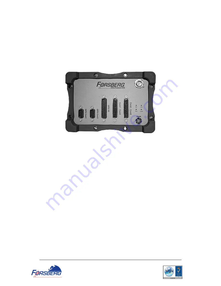
The following figure shows the front panel of the MICROpod providing connectivity to the
serial interfaces, GPS antenna connection, power as well as the LED indicators.
Figure 1 MICROpod connector panel
6.2
Required Equipment
The following equipment is required to set up the MICROpod for comms and to compute a
position.
Power source capable of providing 12vDC
Power supply cable (provided in kit)
GNSS antenna (x2 for MICROpod-HDG)
A quality coaxial cable
Data communication equipment capable of serial communications
Serial cable (provided in kit)
6.3
Selecting a GNSS antenna
An active antenna is required because of its low-noise amplifier (LNA) boost the power of
the incoming signal to compensate for the line loss between the antenna and the receiver.


