MICROpod User Manual
A0016-09-0001
Version Number: 4.00
Page 6
Template Version: 2.01
Revision Date: 24.06.2013
Forsberg Services Limited
Company Registration No: SC104949
Registered Office: Forsberg Services Ltd, 1 East Craibstone Street, Aberdeen, AB11 6YQ
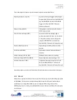
The strobe signals include an input and several outputs as described below:
Mark Input (Event 1, Event 2)
A pulse on this input triggers certain logs to
be generated. (Please refer to the MARKPOS
log, the MARKTIME log and the ONMARK
trigger in the NovAtel OEMV Firmware
Reference Manual)
Measure Output (MSR)
Falling edge is synchronised with internal
GNSS measurements
Pulse Per Second Output (PPS)
A pulse for which the leading edge is
synchronised with GPS time. For the OEMV-
3, the polarity and period is configurable
using the PPSCONTROL command (see
NovAtel OEMV Firmware Reference Manual)
Position Valid Output (PV)
High when good GNSS position and time
solution
Error Output (ERROR)
High when a receiver hardware failure is
detected
LED Red Output (STATUS_RED)
Hardware failure when on or pulsing
LED Green Output (STATUS_GREEN)
Normal operation when pulsing at 1Hz
Variable Frequency (VARF)
Programmable output range from 0 to 20
MHz (see FREQUENCYOUT command in
NovAtel OEMV Firmware Reference Manual)
See cable and pin out section for full details of the Strobe cable and associated strobe pins.
6.9.2
Ethernet
Ethernet is an optional interface. When chosen the Ethernet port on the MICROpod provides
a 10/100Base-T LAN port via a standard 8way RJ45 Connector. Ethernet functionality is
available when a compatible GNSS receiver and adaptor PCB is integrated into the
MICROpod system. Currently, compatible GNSS receivers that include Ethernet functionality
are as follows:


