background image


Appendix A 


Changing Frame IP Address 


The 

ZFCB Control Board

 communicates with the various Integrity AV service cards, 

interpreting control commands and status information to (and from) the network.  Each 
FRM-501 Integrity system frame contains one ZFCB control board.  The board is located 
in the front card bay.  This procedure describes the method to be used by the installer to 
change the Net Address of the ZFCB.   On a dedicated LAN, it is normally not required 
for the installer to change the IP address of a frame. When multiple frames are installed 
on the same LAN over time, it is possible that an IP address conflict could be created as 
new equipment is added.  Each ZFCB ordered in one purchase has a different IP address 
set at the factory.   


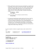
Updating the ZFCB requires removing the FRM-501 from service until the update is 
completed, which only takes a few minutes.  AV service cards will continue to operate, 

but remote control access will be suspended until a cold boot restart is performed

. Cards 

will not be accessible by a control panel until the update is completed. 


Performing this update requires a FRM-501 frame with a ZFCB installed, a DB9 serial 
crossover cable, your PC equipped with an available serial port, and a HyperTerminal 
utility. 


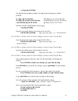
IP Address Rules.  All Integrity system frames and control panels must be assigned IP 
Address values which do not violate the subnet mask restrictions.  The normal subnet 
mask is 255.255.255.0, which requires that all Integrity products must have identical 
values in the first three bytes of the IP Address, with the fourth byte being a unique value 
between 0 - 255, such that no two devices on the LAN have the same IP Address.  
Example:  192.168.0.86 and 192.167.0.150 would not communicate, but 192.168.0.86 
and 192.168.0.150 would communicate correctly. 
  
Each ZFCB card has an IP address, subnet mask, and gateway that can be modified by 
the installer using the following procedure. 
  

Integrity FRM-501 Compact System Frame User Manual 

11 

Summary of Contents for Integrity FRM-501

Page 1: ...Integrity FRM 501 Compact System Frame User Manual Revised Dec 1 2004 Fortel DTV 3305 Breckinridge Blvd Suite 118 Duluth GA 30096 USA 770 806 0234 Integrity FRM 501 Compact System Frame User Manual 1 ...

Page 2: ... one to four AV cards and either a blank faceplate or a local control panel model RCP 502 Configurations FRM 501 Blank faceplate and ZFCB controller card installed four AV card slots FRM 501 with RCP 502 Local control panel and ZFCB controller card installed four AV card slots Integrity FRM 501 Compact System Frame User Manual 2 ...

Page 3: ...he LAN for all AV cards installed in FRM 501 FRM 504 or FRM 304 frames equipped with a ZFCB controller PSU 502 External redundant power supply module It plugs into the 12V DC connector on the rear of the FRM 501 frame If the integral main power supply should fail the PSU 502 will carry the load until the frame can be removed from service for repair of the failed integral supply Integrity FRM 501 C...

Page 4: ...t System Frame with rack mount ears attached Instructions Hardware kit with rear rack mount brackets and all mounting screws Short Adapter Bracket Qty 2 Long Extension Bracket Qty 2 Clip Nut 2 10 32 x 1 Black screws Qty 6 10 32 x Bright Screws Qty 6 Integrity FRM 501 Compact System Frame User Manual 4 ...

Page 5: ...e baseline of the ZFCB card J1 is at the right hand end below the ZFCB nearest the fan J2 is at the left head end below the ZFCB farthest from the fan Connect the LAN jumper cable to J1 Connect the PWR cable to J2 Route these cables to the front of the frame keeping them under the ZFCB card as you re install it in its card guides and sockets Retain the ZFCB in its socket by locking the two card ej...

Page 6: ... require a simple rule to be followed to activate the full feature set of each card The rule is this Video in slot N Audio in slot N 1 Simply put this means that if slot N 1 then slot N 1 2 In the FRM 501 frame a related AV pair can be used in 1 and 2 or 2 and 3 or 3 and 4 but not in 4 and 1 Once the slot has been selected remove its blank cover plate by loosening the two captive screws and pullin...

Page 7: ...rarily affix one extension rail to the rear equipment rack rails Mark the extension rail hole which lines up with the slot in the short bracket Remove the extension bracket from the rack and attach a clip nut at the marked position on the extension Reinstall the extension rail attaching it to the rear equipment rack rail using a single black finish 10 32 x 1 screw then securing the extension to th...

Page 8: ... power source may be added by connecting it to the unswitched 12V DC input connector on the rear of the frame Fortel DTV offers a suitable supply as an optional accessory model PSU 501 Other 12V DC 10A supplies may also be used When an external 12 VDC supply is connected and power applied to it the frame will remain on even if the AC main switch is turned off 1 2 3 4 Fuse Holder AC Power Input DC ...

Page 9: ...al control panel is installed and network communication is not required you must either install a crossover cable between the two RJ45 connectors or connect both to a 100 Mbps Ethernet switch When both connections are made to the Ethernet switch the control panel may also be used to serve as a remote for all other Integrity products on the network Connecting Genlock Reference An external black bur...

Page 10: ... control card is booting The green LINK lamp will light if the Ethernet connection is good The green ACT lamp lights only when a command is received from or sent to the network AC Power Switch OFF Position ON Position Front Panel Status LEDs System fault or booting Network is connected ZFCB transmitting receiving ACT ATTN LINK Integrity FRM 501 Compact System Frame User Manual 10 ...

Page 11: ...l continue to operate but remote control access will be suspended until a cold boot restart is performed Cards will not be accessible by a control panel until the update is completed Performing this update requires a FRM 501 frame with a ZFCB installed a DB9 serial crossover cable your PC equipped with an available serial port and a HyperTerminal utility IP Address Rules All Integrity system frame...

Page 12: ...able serial port to the DB9M connector located on the front edge of the ZFCB control board 3 Open a HyperTerminal window on your PC and set session variables to the following values 38400 Bits per second 8 Data bits N Parity 1 Stop Bit None Flow Control 4 In the connection dialog window press ENTER to verify you have established communication with the ZFCB If successful this will be indicated by t...

Page 13: ...ou must re enter the old value Enter the desired Gateway in the format 192 168 0 1 192 168 0 2 ENTER type your new value i e 192 168 0 2 Note If this is a value you do not wish to change you must re enter the old value After entering the new Gateway value the cbconfig utility will display this prompt Press ENTER to enable new settings q to quit without using Press ENTER to accept the new settings ...

Page 14: ... ZFCB Make sure the ZFCB card is still seated securely in its card socket and that the card locks are fully engaged after removing the serial cable Replace the EMI shield cover using the nine Phillips head countersink screws oriented so that the LED status array is visible through the cover when secured Verify that the frame power supplies are switched on and replace the snap on front cover The RC...

Reviews: