background image

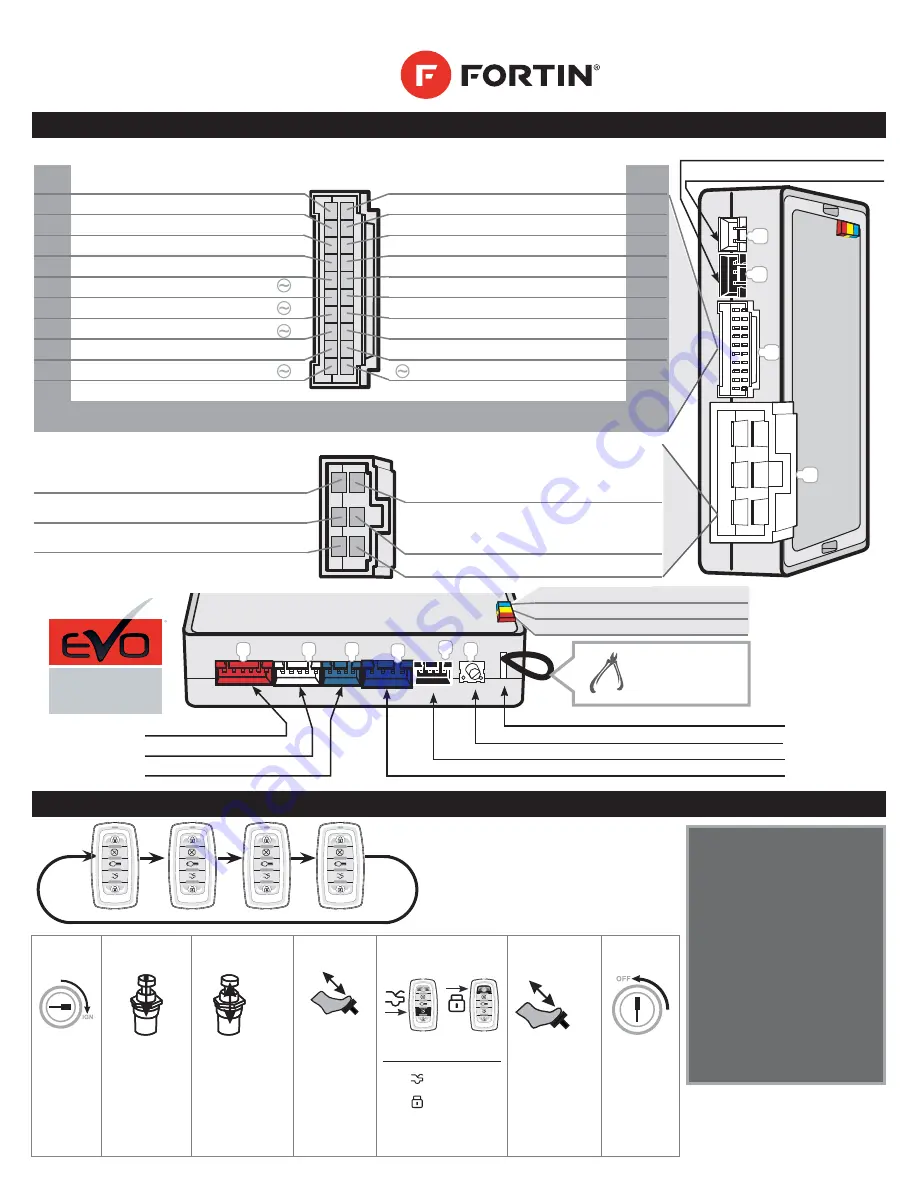
ALL-IN-ONE DATA INTERFACE
REMOTE STARTER / ALARM

QUICK 

INSTALLATION GUIDE

   FTX75  

D

C

B

H

I

J


(6-PIN) 

BYPASS RELAY

(5-PIN) 

CAN-BUS

(4-PIN) 

RS-232 DATA-LINK & FLASH-LINK UPDATER PORT

BYPASS PROGRAMMING BUTTON

REMOTE STARTER PROGRAMMING LED

CUT LOOP FOR 

AUTOMATIC

TRANSMISSION 

MODE.

Red

White

Blue

Blue

Black

LED Blue

CAN ACTIVITY

LED Yellow

IGNITION ON

LED Red

BYPASS DATA

E6

A

F

G

E

(+) Foot Brake

Black

In

750

mA

(-) Parking Light

Pink

Out

750

mA

(-) Trunk Release

Yellow/Black

Out

(-) Hand Brake

Brown/White

In

(-) Hood Status 

Pink/Black

In

Bypass confi g.

Purple/Yellow

Bypass confi g.

Green/White

Bypass confi g.

Green/Red

Bypass confi g.

White/Black

Out

Bypass confi g.

Lt.Blue

Ground

Black

In

(+) Ignition

Pink

Out

(+) Starter

Yellow

Out

Out

White

(+) ParkLight/IGN2
/ACC/START 

Programmable Output 
(FUNCTION 2 & 31)

Out

Orange

(+) ACC / IGN2

Programmable Output 
(FUNCTION 2 & 31)

In

Red

(+) 12V

In

Yellow

(+) 

Bypass 

Ignition

Out

Purple

(-) Lock/Arm

750

mA

Out

Purple/White

(-) Unlock/Disarm

750

mA

Out

Green

(-) Ignition

750

mA

Out

White

(-) Start

750

mA

Out

Orange

(-) Disarm

750

mA

Out

Orange/Black

(-) Horn/Siren

750

mA

Out

Dk.Blue

(-) GWR

750

mA

In

Red/Blue

Bypass confi g.

Lt.Blue/Black

Bypass confi g.

750 mA MAXIMUM OUTPUT.

 Do not exceed the maximum current or permanent damage to the module 

will occur that will not be covered under warranty.


(6-PIN) 

POWER CONNECTOR

(20-PIN) SECONDARY 

CONNECTOR

Copyright © 2014,  

FORTIN AUTO RADIO INC

ALL RIGHTS RESERVED

MADE IN CANADA

REV.:20141003

A1

E1

(3-PIN) 

Shock Sensor 

(2-PIN) 

Valet/Programming Button

A20

WIRING / CONNECTION GUIDE

PROGRAMMING REMOTE TRANSMITTER(S)

The system can learn up to a maxi-
mum of 4 transmitters.
Any transmitters can be stored in 
more than 1 memory slot.
When a 5th transmitter is learned 
the 1st remote is erased (FIFO).

Black

White

White

White

(4-PIN) 

ANTENNA

(4-PIN) 

DATA-LINK ANTENNA

STEP 

1

STEP 

2

STEP 

3

STEP 

4

STEP 

5

STEP 

6

STEP 

7

x5

x1


x1

Turn the 

Ignition 

on.

Press and 

hold

the valet-

switch 

until the LED 

fl ashes, then 

release.

Press and 

release the 

valet-switch 

fi ve time. The 

park-lights 

will fl ash to 

confi rm.

Press and 

release the 

brake pedal 

once.

On each Transmitter 

press and release 

the 

 button then 

press and release 

the   button. The 

park-lights will fl ash 

to confi rm.

Press and 

release the 

brake-pedal 

once.

Turn the 

Ignition 

off.


WWW.FORTIN.CA

ONE

EVO-ONE

Summary of Contents for EVO-ONE FTX75

Page 1: ...Horn Siren 750mA Out Dk Blue GWR 750mA In Red Blue Bypass config Lt Blue Black Bypass config 750 mA MAXIMUM OUTPUT Do not exceed the maximum current or permanent damage to the module will occur that will not be covered under warranty 6 PIN POWER CONNECTOR 20 PIN SECONDARY CONNECTOR Copyright 2014 FORTIN AUTO RADIO INC ALL RIGHTS RESERVED MADE IN CANADA REV 20141003 A1 E1 3 PIN Shock Sensor 2 PIN Val...

Page 2: ... 2 ot 3 is activated 10 11 Confirmation 1st LOCK UNLOCK silent 2nd LOCK UNLOCK sound Antenna LED active LOCK UNLOCK sound always Antenna LED disabled Antenna LED disabled with ignition 12 Sound Confirmation Horn only No sound Siren only 13 Confirmation Pulse Long Short 14 Alarm Starter Options Alarm disabled Remote starter enabled Alarm Remote starter enabled Alarm enabled Remote starter disabled 15 ...

Page 3: ...t No special application Priority on function 2 Special application Function 2 all option not available White Parking Light White Parking Light Orange Accessory Orange Ign 2 White wire E1 Enable at ground out disable with vehicle ignition off White wire E1 Trunk Output Pink Ignition Pink Ign 1 Yellow Start Yellow Start 32 Ground Out Dk Blue Ground out Shut down 1 second after remote start run time...

Page 4: ...ress and hold the LOCK and START buttons for 1 second The remote s Green LED will flash and beep once to confirm The parking lights will flash twice Put the Remote Starter alarm into Valet Remote Start the vehicle Open the hood Press the brake pedal Turn the key to the ignition position Disable Ready Mode manual transmission The manufacturer will accept no responsibility for any electrical damage ...

Page 5: ...nfig contournement Vert Rouge Config contournement Blanc Noir Out Config contournement Bleu Pâle Ground Noir In Ignition Rose Out Démarreur Jaune Out Out Blanc Lumières de stationnement ou Ignition2 ou Accessoire ou Démarreur Sortie programmable FONCTION 2 et 31 Out Orange Accessoire ou Ignition2 Sortie programmable FONCTION 2 et 31 In Rouge 12V In Jaune Ignition contournement Out Mauve Verrouille Ar...

Page 6: ... UNLOCK confirmation sonore Antenne DEL active Verrouillage Déverrouil lage avec confirmation sonore DEL de l antenne non active DEL de l antenne off avec l ignition 12 Son de Confirma tion Klaxon seulement Pas de son Sirène seulement 13 Pulse de Confirma tion Long Court 14 Option alarme et démarreur Alarme non actif Démarreur actif Alarme active démarreur actif Alarme active démarreur non actif 15 Re...

Page 7: ...res de sta tionnement Blanc Lumières de sta tionnement Orange Acces soire Orange Ignition2 Fil Blanc E1 S active en même temps que la masse d activation désactive avec ignition off Fil Blanc E1 Sortie Valise Rose Ignition Rose Ignition1 Jaune Démar reur Jaune Démar reur 32 Ground Out Bleu Foncé Masse d activation S éteint 1 sec après le temps de fonctionnement du démarreur Bleu Foncé Masse d activ...

Page 8: ...z sur le bouton VALISE en moins de 12 secondes pour appuyez simultanément sur le bouton VERROUILLAGE et DÉMARRAGE pour 1 seconde jusqu à ce que les lumières de stationnement clignotent 2 fois Mettre le démarreur à distance alarme en mode Valet Ouvrir le capot Faites démarrer le moteur par le biais de la télécommande Actionner la pédale de frein Tourner la clé de contact en position d allumage Les ...

Reviews: