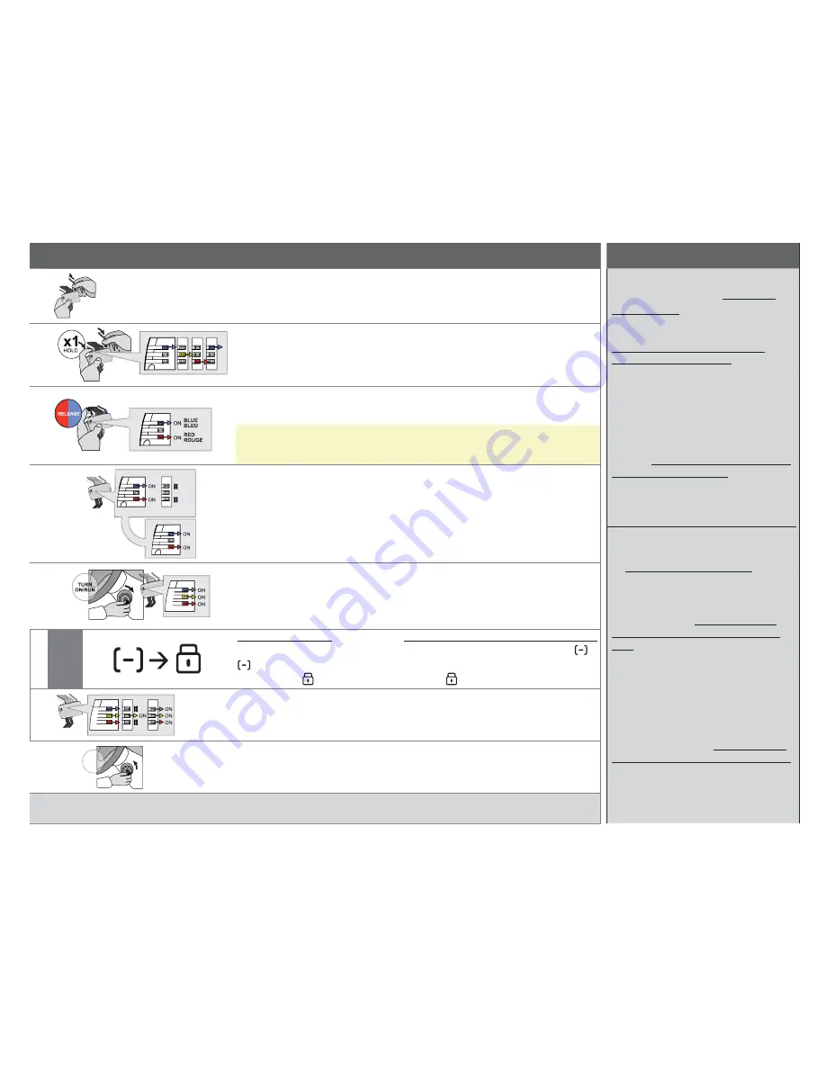
PROGRAMMING REMOTE TRANSMITTER(S) I PROGRAMMATION DES TÉLÉCOMMANDES
WARNING | MISE EN GARDE
1
Unplug
the 4 Pin (Data-Link)
connector.
Débranchez
le connecteur 4 pins (Data-
Link).
REMOTE STARTER INSTALLATION
ONLY COMPATIBLE WITH AUTOMATIC
TRANSMISSION VEHICLES.
SEE VEHICLE FIT GUIDE AT :
http://fortin.ca/en/features/stand_
alone_remote_starter.html
Neither the manufacturer or distributor
of this module is responsible for
damages of any kind either indirectly
or directly caused by this module,
except for the replacement of this
module in case of manufacturing
defects. This module must be installed
by a qualifi ed technician. This
instruction guide may change without
notice. Visit www.fortin.ca to obtain
the latest version.
INSTALLATION DU DÉMARREUR À
DISTANCE COMPATIBLE AVEC VÉHICULE
À TRANSMISSION AUTOMATIQUE
SEULEMENT.
VOIR LA LISTE DES VÉHICULES
SUPPORTÉS AU : http://fortin.ca/fr/
features/stand_alone_remote_starter.
html
Ni le manufacturier, ni le distributeur
ne se considèrent responsables
des dommages causés ou ayant
pu être causés, indirectement ou
directement, par ce module, excepté le
remplacement de ce module en cas de
défaut de fabrication. Ce module doit
être installé par un technicien qualifi é.
Ce guide d’instruction peut faire
l’objet de changement sans préavis.
Consultez le www.fortin.ca pour voir la
plus récente version.
2
Press and hold
the programming
button:
Reinsert the 4-Pin (Data-Link)
connector.
Appuyez et maintenir enfoncé
le bouton de
programmation:
Insérez le connecteur 4 pins (Data-Link)
3
Release
the programming button
when LEDs are BLUE & RED.
Relâchez
le bouton de programmation
quand les DELs sont BLEU et ROUGE
sont allumées.
If the LED are not solid BLUE and
RED disconnect the 4-Pin connector
(Data-Link) and go back to step 1.
Si les LED ne sont pas ALLUMÉES BLEU
et ROUGE, débranchez le connecteur 4 pins
(Data-Link) et allez au début de l’étape 1.
4
OFF
OFF
Press and hold
the programming
button until the Blue and RED
LED turn back ON.
Pesez
et
gardez appuyé
le bouton de
programmation jusqu’à ce que les DELS
BLEU et ROUGE se rallument.
The Blue and Red LED will go Off
and back On.
Les DELs BLEU et ROUGE s’éteignent et
se rallument.
5
LOCK
ACC ON
PUSH
ST
ART
IGN
Turn
the key to the ON/RUN
position.
Tournez
la clé à la position ON/RUN.
The Blue, Yellow and Red LEDs
will turn On.
The antenna will fl ash rapidly.
Les DELs BLEU, JAUNE et ROUGE
s’allument.
L’antenne clignote rapidement.
6
On each Transmitter
press and release the
button then press and
release the button.
SUR CHACUNE DES TÉLÉCOMMANDES:
Appuyez et relâchez le bouton
ensuite appuyez et relâchez le
bouton .
The Blue and Red LEDs will fl ash
once everytime to confi rm.
Les DELs BLEU et ROUGE clignoterons
une fois pour confi rmer.
7
ST
AR
T
OFF
TURN
OFF
Turn
the Ignition to the OFF posi-
tion and test the installation.
Tournez
la clé à OFF et testez l’instal-
lation.
The remote is now programmed.
La télécommande est maintenant
programmée.


