1
2
GM-SL2
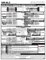
WIRING / CONNECTION GUIDE
WIRING / CONNECTION GUIDE
See wiring schematic configuration
Lock
12V Battery
(+)
Lt. Blue/Black
Unlock Driver 1
Ground
(-)
White/
Black
Ignition
Data-Link
Pink/Black
(-) While running
Data-Link
Green
Door trigger
Orange/Black
Data OBD2
Purple/White or Purple/Black
Bypass PK
Yellow/Black
Lt. Blue
Red
Trunk
White
Black
Unlock Driver 2
Pink
Blue
Parking light
Blue
White
N./C.
Orange
Purple
Data BCM
Yellow
Bypass P 3
K
DATA INTERFACE MODULE SELF-LEARNING FOR SECURITY SYSTEM AND / OR REMOTE STARTER.
GM-SL2
3
Connect wire to vehicle
Connect wire to Remote-Starter/Alarm
INPUT
OUTPUT
2
3
4
5
6
7
2
IGN
START
OFF
8
9
10
IGN
START
OFF
IGN
START
OFF
LED
Programming
button
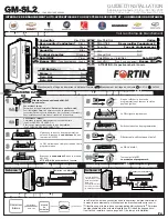
Press and hold the programming
button. Plug in the
in the GM-SL2 interface.
connector 1
Plug the
into the
GM-SL2 interface.
connector 2
The LED will turn on, indicating
the beginning of programming.
While holding the programming
button, turn the key to the ignition
position.
The LED will flash rapidly.
Release the programming button.
Start the vehicle with the key.
The LED will turn off.
Turn the key OFF.
The interface is programmed.
1
Make the connections of the GM-SL2 to the
vehicle:
1.A
1.B
Connector 2 (White):
(I) Locate the wiring type for the vehicle on the
VEHICLE FIT GUIDE (P.2)
(II) Make the connections associated with the vehicle in the
WIRING SCHEMATIC CONFIGURATION (P.3)
N./C.
Starter or alarm
Data Link Port
1
P.1
Plan 1
START HERE
INSTALLATION AND PROGRAMMATION INSTRUCTIONS
INSTALLATION AND PROGRAMMATION INSTRUCTIONS
Starter or alarm
2
1
Red
+12V
Black
Plan 2
Cut off one plug of the
Data-Link connector,
connect the red wire
to +12V and the black
wire to ground.
Connector 1 (Black):
Determine the type of installation:
DATA-LINK (
)
INSTALLATION WITH
See plan 1, below
DATA-LINK (See plan 2, below)
INSTALLATION WITHOUT
WHAT IS DATA-LINK?
WHAT IS DATA-LINK?
2 way
Starter
Alarm
The Data-Link is a connection between the remote-Starter/Alarm and the
Bypass/Interface module.
This connection eliminates all other connections
between devices by using bidirectionnal communication.
It reduces the
number of connections thus reducing installation error, and eliminates the risk
of theft.
It very easy to install and saves up 60% of the installation time.
Bypass
Data-Link
1
2
Copyright © 2006, FORTIN AUTO RADIO INC
ALL RIGHTS RESERVED
INSTALLATION WITH DATA-LINK
INSTALLATION WITH DATA-LINK
INSTALLATION WITHOUT DATA-LINK
INSTALLATION WITHOUT DATA-LINK
WARNING: Connector 2 can be easily plugged in backwards.
WARNING: Connector 2 can be easily
plugged in backwards.
(Type 3 only)
(Type 3 only)
INSTALLATION GUIDE
Made in Canada - V1.8.g - 02 / 10 / 2007
W e b
s i t e :
h t t p : / / w w w . i f a r . c a


