background image

FIM-7921F Interface Module Guide

FortiGate-7000F Series

Summary of Contents for FIM-7921F

Page 1: ...FIM 7921F Interface Module Guide FortiGate 7000F Series ...

Page 2: ...t fortinet com FORTINET TRAINING CERTIFICATION PROGRAM https www fortinet com support and training training html NSE INSTITUTE https training fortinet com FORTIGUARD CENTER https fortiguard com END USER LICENSE AGREEMENT https www fortinet com doc legal EULA pdf FEEDBACK Email techdoc fortinet com May 10 2021 FIM 7921F Interface Module Guide 6 2 6 01 626 669631 20210510 ...

Page 3: ... and removing a FIM 7921F module from a chassis 19 Troubleshooting 24 FIM 7921F does not startup 24 FIM 7921F status LED is flashing during system operation 24 Quick FIM 7921F configuration 25 Registering your FortiGate 7000 series products 25 Choosing the configuration tool 25 Changing network settings 25 Cautions and warnings 27 Environmental specifications 27 Safety 28 Regulatory notices 29 Fed...

Page 4: ...10 2021 New section Changing the FIM 7921F 19 and 20 interfaces on page 9 April 8 2021 Added average power consumption March 30 2021 Minor fixes March 17 2021 Initial release FIM 7921F 6 2 6 Interface Module Guide 4 Fortinet Technologies Inc ...

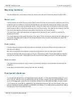
Page 5: ...faces 1 to 18 and two 400GigE QSFP DD fabric channel data network interfaces 19 and 20 Interfaces 1 to 18 can be connected to 100Gbps data networks Interfaces 19 and 20 can be connected to 400Gbps data networks You can also change the interface type of interfaces 19 and 20 and change the speeds of all of the data interfaces The FIM 7921F also includes two 100 GigE QSFP28 base channel management in...

Page 6: ... Close the module levers and move the power sliders to their bottom position to lock the module levers and turn the module power switch on Move the power sliders to the top position to unlock the module levers and turn the module power switch off Gently push the power sliders down to make sure they are in their bottom position If the module LEDs do not light the module is not receiving power If th...

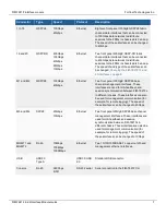
Page 7: ...E QSFP28 base channel management interfaces These interfaces are used for HA heartbeat and session synchronization between FIM 7921Fs in different chassis These interfaces can also be used for management communication for example for remote logging The speed of these interfaces can be changed to 40Gbps M3 and M4 SFP28 25Gbps 10Gbps Ethernet Two front panel 25GigE SFP28 base channel management inte...

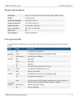
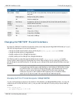
Page 8: ...tioning normally LED State Description STATUS Off The FIM 7921F is powered off Green The FIM 7921F is powered on and operating normally Flashing Green The FIM 7921F is starting up ALARM Red Major alarm Amber Minor alarm Off No alarms HA Off The FIM 7921F is operating in normal mode Green The FIM 7921F is operating in HA mode Red A failover has occurred POWER Green The FIM 7921F is powered on and o...

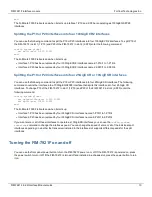
Page 9: ... CR or 10GigE SR interfaces All of these operations except changing the interface speed using the config system interface command require a system restart Fortinet recommends that you perform these operations during a maintenance window and plan the changes to avoid traffic disruption For example you can change interface types and split interfaces as a single operation You should change interface ...

Page 10: ...igE QSFP28 interface then splits this interface into four 25 GigE CR interfaces To change P19 of the FIM 7921F in slot 1 1 P19 and P20 of the FIM 7921F in slot 2 2 P20 enter the following command config system global set qsfpdd 100g port 1 P19 2 P20 set split port 1 P19 2 P20 end The FortiGate 7000F reboots and when it starts up l Interface 1 P19 has been replaced by four 25GigE CR interfaces name...

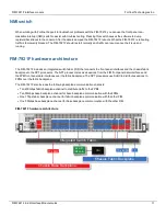
Page 11: ...fabric backplane to the NP7 processors The NP7 processors receive sessions from the FIM front panel data interfaces and the FPM front panel data interfaces over the fabric backplane The NP7 processors use SLBC to distribute sessions to FPMs over the fabric backplane The FIM 7921F also includes the following backplane communication channels l Ten 400Gbps fabric backplane channel to distribute traff...

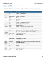
Page 12: ...lly Off The FIM 7921F is powered off 1 to 20 M1 and M2 Green The correct cable is connected to the interface and the connected equipment has power and is connected at 400Gbps 100Gbps or 40Gbps Flashing Green Network activity at the interface Off No link is established M3 and M4 Green The correct cable is connected to the interface and the connected equipment has power Flashing Green Network activi...

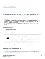
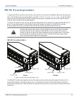
Page 13: ...ischarge ESD preventive wrist strap with connection cord FIM 7921Fs must be protected from static discharge and physical shock Only handle or work with FIM 7921Fs at a static free workstation Always wear a grounded electrostatic discharge ESD preventive wrist strap when handling FIM 7921Fs Handling the transceivers by holding the release latch can damage the connector Do not force transceivers int...

Page 14: ... slot On some FIM modules there may be very little clearance between the front panel interfaces and the module lever on the right side of the FIM 7921F In fact you may have to remove network connectors from some front panel interfaces to open the module lever In most cases you should remove all network connectors from the front panel before opening the module levers to remove an FIM module from a ...

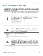
Page 15: ...module to get power and start up If the module is not receiving power all LEDs remain off FIM 7921F modules are hot swappable This procedure is the same whether or not the chassis is powered on Do not carry the FIM 7921F module by holding the module levers or secure screws When inserting or removing the FIM 7921F from a chassis slot handle the module by the front panel The levers are not designed ...

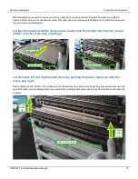
Page 16: ...module into the slot stop at about 1 2 inches from fully inserting it Module levers Module levers Slide in slowly Stop position 3 Unlock the left and right module levers by pushing the power sliders up until the levers pop open Before sliding the final portion of the module into the chassis fully open both levers by pushing the power sliders up Fully open both levers to avoid damaging the lever me...

Page 17: ...erted into chassis Apply moderate force to push the module slowly into the slot Stop Position Levers engage with chassis 5 Close both levers by pushing them into contact with the module front panel Closing the levers draws the module into the chassis slot and connects the module rear connectors to the chassis backplane The design of the levers leaves gaps to compensate for tolerances So even when ...

Page 18: ...lly tighten the two secure screws Do not use a power screwdriver because the high torque and speed can damage the chassis or screw thread After tightening both secure screws the module is fully seated in the chassis slot and the module connectors are fully in contact with the chassis backplane After tightening both secure screws the module is fully engaged with the chassis Tighten by hand Fully ti...

Page 19: ...owered on check the modle LEDs to verify that the module is operating correctly LED Normal operation state Status Green Alarm Off HA Off Power Green Shutting down and removing a FIM 7921F module from a chassis This procedure describes how to shut down and remove a FIM 7921F module from FortiGate 7000 chassis The procedure includes photographs to illustrate the procedure steps The photos were taken...

Page 20: ...from static discharge and physical shock Only handle or work with FIM 7921Fs at a static free workstation Always wear a grounded electrostatic discharge ESD preventive wrist strap when handling FIM 7921Fs An ESD wrist strap is not visible in the photographs below because they were taken in an ESD safe lab environment 1 Shut down the module operating system properly To avoid potential hardware prob...

Page 21: ...lly loosen the secure screws otherwise the levers may be damaged when used to eject the module from the chassis slot Do not use a power screwdriver because the high torque and speed can damage the chassis or screw thread Use a Phillips screwdriver to loosen both screws Fully loosen both screws by hand FIM 7921F 6 2 6 Interface Module Guide 21 ...

Page 22: ...t levers by pushing the power sliders up until the levers pop open Push the power sliders up to fully open both levers If the chassis is powered on this step turns off the module s power Levers pop open Power slider up Power slider up FIM 7921F 6 2 6 Interface Module Guide 22 ...

Page 23: ...levers and eject the module from the chassis Levers opened Rotate to open Module ejects Module ejected 6 Hold the levers to slide the module part way out of the chassis slot Then grasp the module by the sides and carefully slide it out of the slot FIM 7921F 6 2 6 Interface Module Guide 23 ...

Page 24: ...with FortiOS Connect to the FIM 7921F console and try cycling the power to the board If the BIOS starts up interrupt the BIOS startup and install a new firmware image See your FortiGate 7000 chassis system guide for information about accessing and installing firmware on individual modules If this does not solve the problem contact Fortinet Technical Support FIM 7921F status LED is flashing during ...

Page 25: ...by visiting https support fortinet com To register enter your contact information and the serial numbers of the Fortinet products that you or your organization have purchased Choosing the configuration tool You can use either the GUI or the Command Line Interface CLI to configure the FIM 7921F Some basic configuration settings can only be done from the CLI You can connect to the GUI using HTTP or ...

Page 26: ...onnecting MGMT1 of the module in slot 1 to your network and browsing to https 192 168 1 99 Log into the GUI using the admin account with no password Go to Network Interface and configure the FIM 7921F interfaces to connect to your networks FIM 7921F 6 2 6 Interface Module Guide 26 ...

Page 27: ...ical loading Chargement Mécanique Montage de l équipement dans le rack doit être telle qu une situation dangereuse n est pas lié à un chargement mécanique inégal Circuit Overloading Consideration should be given to the connection of the equipment to the supply circuit and the effect that overloading of the circuits might have on overcurrent protection and supply wiring Appropriate consideration of...

Page 28: ...ushing or cutting it can result in an explosion Leaving a battery in an extremely hot environment can result in leakage of flammable liquid gas or an explosion If a battery is subjected to extremely low air pressure it may result in leakage of flammable liquid gas or an explosion WARNUNG Lithium Batterie Achtung Explosionsgefahr bei fehlerhafter Batteriewechsel Ersetzen Sie nur den gleichen oder g...

Page 29: ...se harmful interference in which case the user will be required to correct the interference at his own expense WARNING Any changes or modifications to this product not expressly approved by the party responsible for compliance could void the user s authority to operate the equipment Industry Canada Equipment Standard for Digital Equipment ICES Canada CAN ICES 3 A NMB 3 A This digital apparatus doe...

Page 30: ...同梱し ている電源コ ード は本製品の専用電源コ ード と し て利用し 他の製 品に使用し ないでく ださ い Bureau of Standards Metrology and Inspection BSMI Taiwan The presence conditions of the restricted substance BSMI RoHS table are available at the link below 限用物質含有情況表 RoHS Table 請到以下 網址下載 https www fortinet com bsmi 此為甲類資訊技術設備 於居住環境中使用時 可能會造成射頻擾動 在此種情況下 使用者會被要求採取某些 適當的對策 英屬蓋曼群島商防特網股份有限公司台灣分公司 地址 台北市內湖區行愛路176號2樓 電話 02 27961666 China 此为A级产品 在生...

Page 31: ...tinet enters a binding written contract signed by Fortinet s General Counsel with a purchaser that expressly warrants that the identified product will perform according to certain expressly identified performance metrics and in such event only the specific performance metrics expressly identified in such binding written contract shall be binding on Fortinet For absolute clarity any such warranty w...

Reviews: