background image

10

11

.

.

Installation

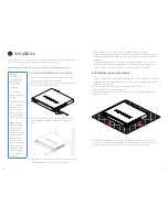
To install the FortiGate unit into a rack

1.  Ensure that the 

FortiGate unit

 is placed on a stable 

surface prior to rack-mount installation.

2.  Attach the provided 

rack-mount brackets 

to the sides of 

the unit using the provided 

screws

.

3. Position the 

FortiGate unit 

in the rack. Ensure there is 

FOPVHISPPNBSPVOEUIFVOJUUPBMMPXGPSTVGmDJFOUBJS
nPX

4. Line up the

 rack-mount bracket holes

 to the holes on the 

rack and ensure that the 

FortiGate unit 

is level.

Caution:


Electrostatic 
discharge (ESD) 
can damage 
your Fortinet 
equipment. 

Do not place 
heavy objects on 
the unit.

To avoid personal 
injury or damage 
to the unit, it is 
recommended 
that two or more 
people install the 
unit into the rack.

Note: 

If the unit 

has a redundant 
power supply, 
each power 
cable should be 
connected to a 
different power 
source. In this 
way, if one power 
source fails, the 
other may still be 
operational and 
the unit will not 
lose power.

5.  Finger tighten 

four rack-mount screws

 to attach the unit to the rack.

 6.  Verify that the spacing around the 

FortiGate unit 

conforms to requirements and 

that the unit is level, then tighten the rack-mount screws with an appropriate 
screwdriver.

7.  Using the provided 

power cable

, plug the cable into the rear of the unit, and 

then into a grounded electrical outlet or a separate power source such as an 

uninterruptible power supply

 (UPS) or a 

power distribution unit

 (PDU).

7RLQVWDOOWKHXQLWRQDÁDWVXUIDFH

1. Ensure that the surface onto which the 

FortiGate unit 

to be installed is clean, level, 

and stable and that there is at least 

1.5 inches (3.8cm)

 of clearance on all sides to 

BMMPXGPSBEFRVBUFBJSnPX

2. Attach the provided 

rubber feet 

to the bottom of the 

FortiGate unit

.

3. Place the unit in the designated location.
4.  Verify that the spacing around the 

FortiGate unit

 conforms to requirements and 

that the unit is level.

5.  Using the provided 

power cable

, plug the cable into the rear of the unit, and 

then into a grounded electrical outlet or a separate power source such as an 

uninterruptible power supply

 (UPS)


or a 

power distribution unit

 (PDU).

The 

FortiGate unit 

DBOCFQMBDFEPOBOZnBUTVSGBDFPSNPVOUFEJOBOZTUBOEBSE

inch rack unit with the provided 

rack-mount brackets

 and 

screws

.


Please read the Cautions and Warnings section prior to installing your device.

1.5in

1.5in

3

Summary of Contents for FortiGate 240D

Page 1: ... FortiGate 240D QuickStart Guide ...

Page 2: ...T FYQSFTTMZ JEFOUJmFE JO such binding written contract shall be binding on Fortinet For absolute clarity any such warranty will be limited to performance in the same ideal conditions as in Fortinet s internal lab tests Fortinet disclaims in full any covenants representations and guarantees pursuant hereto whether express or implied Fortinet reserves the right to change modify transfer or otherwise...

Page 3: ...P Address Default Gateway Write down details that you may need from your network administrator or ISP Primary Secondary DNS Subnet Mask STATUS POWER ALARM HA USB MGMT MGMT USB CONSOLE WAN 1 WAN 2 DMZ 1 DMZ 2 1 2 3 4 5 6 7 8 11 12 13 14 15 16 17 18 19 20 21 22 23 24 9 10 37 38 39 40 25 26 27 28 29 30 31 32 33 34 35 36 FortiGate 240D QuickStart Guide USB Cable Ethernet Cable 2 Rack Mount Brackets 8 ...

Page 4: ... cable 2 Visit 192 168 1 99 in your web browser 3 Login using username admin and no password 4 Click Wizard in the top right corner 5 POmHVSF ZPVS EFWJDF and save your settings 6 Register your device from the dashboard page Web Browser with Ethernet cable A https LAN Port FortiGate Setup Options 2 Web Browser Setup Wizard p 5 With FortiExplorer p 6 FortiExplorer App POmHVSBUJPO QQ OS X Terminal Em...

Page 5: ...ortiExplorer from http forti net fexp B USB MGMT Terminal Emulation with Console Cable To Connect to the CLI 1 Connect the FortiGate unit console port to the management computer using a console cable 2 Start a terminal emulation program on the management computer Select the COM port and use the following settings Baud Rate 9600 Data bits 8 Parity None Stop bits 1 Flow Control None 3 Press Enter on...

Page 6: ...p to your device from http forti net fexp ios 2 Use your Apple to USB cable to connect to the USB port 3 Launch the FortiExplorer App and select the device model 4 Login using username admin and no password POmHVSF ZPVS EFWJDF 5IJT WFSTJPO EPFT OPU IBWF B XJ BSE iOS with Apple to USB cable D ...

Page 7: ...conforms to requirements and that the unit is level then tighten the rack mount screws with an appropriate screwdriver 7 Using the provided power cable plug the cable into the rear of the unit and then into a grounded electrical outlet or a separate power source such as an uninterruptible power supply UPS or a power distribution unit PDU 7R LQVWDOO WKH XQLW RQ D ÁDW VXUIDFH 1 Ensure that the surfa...

Page 8: ...nted each time that you are inserting a transceiver 4 Hold the sides of the SFP transceiver and slide it into the cage socket until it clicks into place SFP Transceivers Caution Do not force the SFP transceivers into the cage slots If the transceiver does not easily slide in and click into place it may not be aligned correctly or may be upside down If this happens remove the SFP transceiver realig...

Page 9: ...ng data Off No link established Ethernet Ports Speed Green Connected at 1Gbps Amber Connected at 100Mbps Off Connected at 10Mbps or not in use SFP Ports Green Active Flashing green Transmitting receiving data Off No link established Logo Green On Off STATUS POWER ALARM HA USB MGMT MGMT USB CONSOLE WAN 1 WAN 2 DMZ 1 DMZ 2 1 2 3 4 5 6 7 8 11 12 13 14 15 16 17 18 19 20 21 22 23 24 9 10 37 38 39 40 25...

Page 10: ...et LAN Ports 1 40 RJ 45 Switched Gigabit Ethernet ports for connection to your network and the Internet MGMT RJ 45 Client port for management Default IP address 192 168 1 99 RPS Optional connection to a remote power supply FRPS 100 12V 12 5A Power 100 240V AC 50 60Hz 3A MAX STATUS POWER ALARM HA USB MGMT MGMT USB CONSOLE WAN 1 WAN 2 DMZ 1 DMZ 2 1 2 3 4 5 6 7 8 11 12 13 14 15 16 17 18 19 20 21 22 2...

Page 11: ...HV VXULQWHQVLWpV DGDSWp j OD UpJOHPHQWDWLRQ ORFDOH GRLW rWUH LQFRUSRUp GDQV O LQVWDOODWLRQ pOHFWULTXH GX EkWLPHQW D ERUQH GH PLVH j OD WHUUH GRLW rWUH HQ SHUPDQHQFH UHOLpH DX FRQGXFWHXU j UD XUH YHUWH HW MDXQH GH WDLOOH PLQLPXP 6HXO XQ WHFKQLFLHQ TXDOLÀp HVW DXWRULVp j HIIHFWXHU OH UDFFRUGHPHQW Battery 5LVN RI H SORVLRQ LI WKH EDWWHU LV UHSODFHG E DQ LQFRUUHFW W SH R QRW GLVSRVH RI EDWWHULHV LQ D ...

Page 12: ...n Guide 5IF mSTU TUFQT JO QMBOOJOH ZPVS DPOmHVSBUJPO FOUSBMJ FE management tightening security and best practices http forti net systemadmin 5HIHUHQFH POmHVSBUJPO PG your device using the command line http forti net cli FortiOS Handbook FmOJUJWF HVJEF UP DPOmHVSJOH BOE PQFSBUJOH PSUJ04 http forti net handbook Training Services Course descriptions availability schedules and location of training pro...

Reviews: