background image

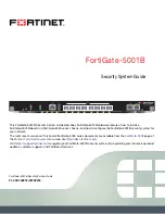
FortiGate-5001B Security System Guide
01-400-134818-20120216

5

http://docs.fortinet.com/

FortiGate-5001B

FortiGate-5001B security system

The FortiGate-5001B security system is a high-performance Advanced 
Telecommunications Computing Architecture (ATCA) compliant FortiGate security system 
that can be installed in any ATCA chassis that can provide sufficient power and cooling. 
You can install FortiGate-5001B boards in a FortiGate-5060 chassis and in selected 
versions of the NEBS-compliant FortiGate-5140-R chassis. 

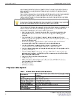
Table 1

 lists FortiGate-5000 

series chassis that can support the FortiGate-5001B board. For most up-to-date list of all 
chassis that can support the FortiGate-5001B board see the FortiGate-5001B Release 
Notes.

For more information about FortiGate-5000 series chassis see the 

FortiGate-5000 

Chassis Guides

 page of the Fortinet Technical Documentation web site.

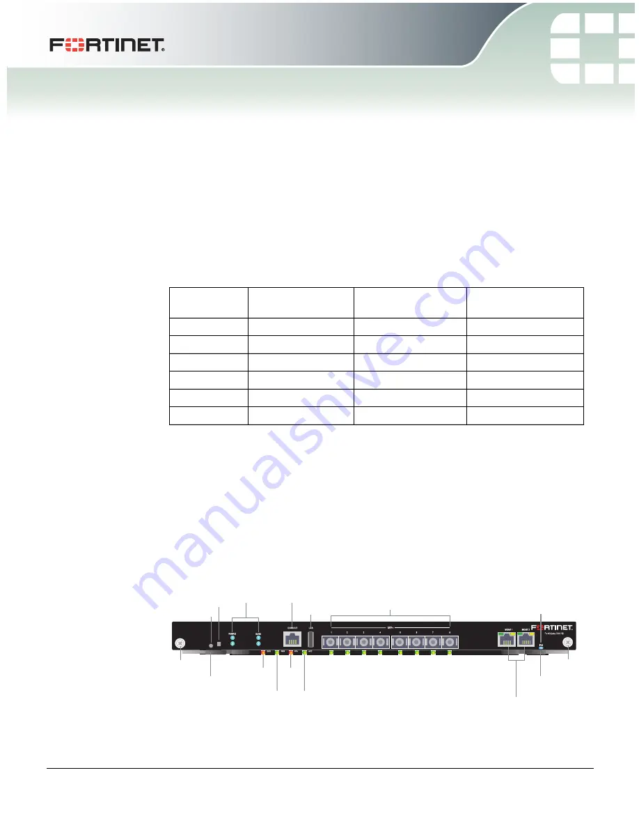
The FortiGate-5001B security system contains eight front panel 10-gigabit SF

P

interfaces, two base backplane 1-gigabit interfaces, and two fabric backplane 10-gigabit 
interfaces. The front panel interfaces can also operate as 1-gigabit SF

P

 interfaces. Use 

the front panel interfaces for connections to your networks and the backplane interfaces 
for communication across the ATCA chassis backplane. The FortiGate-5001B also 
includes two front panel RJ45 10/100/1000 management Ethernet interfaces, one RJ45 
front panel serial management port, and one front panel USB port.

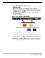
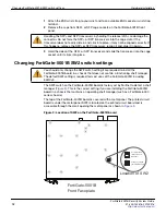
Figure 1: FortiGate-5001B front panel

Table 1:   FortiGate-5000 series chassis that support the FortiGate-5001B board

Chassis 
Model

Hardware ID

System Part Number

Serial Number

FG-5140B

C4GL51-01BD-0000 P09297-01

FG514B3Y12000xxx

FG-5060

C4FN27-01AA-0000

P08588-01

FG50603S1XXXXXXX

FG-5140

C4GL51-01BC-0000 P05355-01

FG51403S0900000X

FG-5140

C4GL51-02BC-0000 P05355-02

FG51403S090010XX

FG-5140

C4DH67-01AA-0000 P05853-01

FG51403S090020XX

FG-5140

C4DH67-02AA-0000 P05853-02

FG51403S1003XXXX

MGMT 1 and MGMT 2

10/100/1000 Copper

Management Interfaces

1 to 8

10 Gig

SFP+ Interfaces

USB

Fabric and Base

network activity

LEDs

RJ-45

Console

Extraction

Lever

Retention

Screw

Extraction

Lever

Retention

Screw

IPM

LED

(board

position)

OOS
LED

STA
LED

PWR
LED

ACC
LED

Factory Use

NMI Switch

Summary of Contents for FortiGate-5001B

Page 1: ...cent versions of this and all FortiGate 5000 series documents are available from the FortiGate 5000 page of the Fortinet Technical Documentation web site http docs fortinet com Visit https support for...

Page 2: ...FortiGate 5000 series equipment Only perform the procedures described in this document from an ESD workstation If no such station is available you can provide some ESD protection by wearing an anti st...

Page 3: ...gs 12 FortiGate 5001B mounting components 14 Inserting a FortiGate 5001B board 15 Shutting down and removing a FortiGate 5001B board 17 Power cycling a FortiGate 5001B board 19 Troubleshooting 20 Fort...

Page 4: ...ing the CLI to configure Transparent mode 30 Upgrading FortiGate 5001B firmware 30 FortiGate 5001B base backplane data communication 32 FortiGate 5001B fabric backplane data communication 32 For more...

Page 5: ...o fabric backplane 10 gigabit interfaces The front panel interfaces can also operate as 1 gigabit SFP interfaces Use the front panel interfaces for connections to your networks and the backplane inter...

Page 6: ...ot forward traffic Two base backplane 1 gigabit interfaces base1 and base2 for HA heartbeat communications across the FortiGate 5000 chassis base backplane Two fabric backplane 10 gigabit interfaces f...

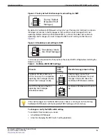
Page 7: ...bps Flashing Green Network activity at base backplane interface 1 or 2 base1 or base2 OOS Out of Service Off Normal operation Amber A fault condition exists and the FortiGate 5001B blade is out of ser...

Page 8: ...p to running mode or from running mode to hot swap This happens when the FortiGate 5001B board is starting up or shutting down Off Normal operation The FortiGate 5001B board is in contact with the cha...

Page 9: ...ortiSwitch 5000 series boards see the FortiSwitch 5000 Series documents on the FortiSwitch page of the Fortinet Technical Documentation website Fabric backplane communication The FortiGate 5001B fabri...

Page 10: ...trusion protection IPS and antivirus when there is a reasonable percentage of P2P packets Firewall and IPsec VPN applications Figure 2 FortiGate 5001B NP4 to interface mapping Traffic between interfac...

Page 11: ...2 SPT interfaces if you want to connect more than 2 front panel interfaces you should purchase and install additional compatible SFP transceivers for these interfaces You can also configure front pane...

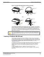
Page 12: ...d is covered with a metal panel The printed circuit board is under the metal panel SW2 is located on the printed circuit board and is accessible through the small opening the metal panel as shown in F...

Page 13: ...n a chassis To change or verify the SW2 switch setting To complete this procedure you need A FortiGate 5001B board A tool for changing the SW2 switch setting optional Table 5 FortiGate 5001B SW2 setti...

Page 14: ...ents to lock the board into place in the slot When locked into place and positioned correctly the board front panel is flush with the chassis front panel The board is also connected to the chassis bac...

Page 15: ...lly tightened for the FortiGate 5001B board to receive power and operate normally If the FortiGate 5001B board is not receiving power the IPM LED glows solid blue and all other LEDs remain off See Fro...

Page 16: ...oard should glide smoothly into the chassis slot If you encounter any resistance while sliding the board in the board could be aligned incorrectly Pull the board back out and try inserting it again 7...

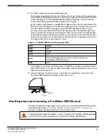
Page 17: ...Gate 5001B firmware starts up During start up the STATUS LED may continue to flash green Once the board has started up and is operating correctly the front panel LEDs are lit as described in Table 6 I...

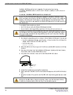
Page 18: ...ork cables the console cable and any USB cables or keys 4 Fully loosen the retention screws on the FortiGate 5001B front panel 5 Unlock the handles by squeezing the handle locks 6 Slowly open both han...

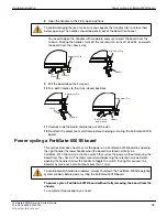
Page 19: ...by opening the right handle the lower handle when the board is installed vertically in a FortiGate 5140 chassis to activate a switch that cycles the power without removing the board from the chassis T...

Page 20: ...ap both handles back into place The board powers up the LEDs light and in a few minutes the FortiGate 5001B board operates normally 8 Fully tighten the retention screws to lock the FortiGate 5001B boa...

Page 21: ...and try cycling the power to the board If the BIOS starts up interrupt the BIOS startup and install a new firmware image If this does not solve the problem contact Fortinet Customer Service and Suppor...

Page 22: ...Troubleshooting Hardware installation FortiGate 5001B Security System Guide 22 01 400 134818 20120216 http docs fortinet com...

Page 23: ...net customer services such as product updates and customer support You must also register your product for FortiGuard services such as FortiGuard Antivirus and Intrusion Prevention updates and for For...

Page 24: ...ute mode Transparent mode In Transparent mode the FortiGate 5001B security system is invisible to the network All of the FortiGate 5001B interfaces are connected to different segments of the same netw...

Page 25: ...t connection between the FortiGate 5001B board and management computer Internet Explorer 6 0 or higher on the management computer Command Line Interface CLI The CLI is a full featured management tool...

Page 26: ...1 IP Netmask 192 168 1 99 24 mgmt2 IP Netmask 192 168 100 99 24 Default route Gateway 192 168 100 1 Device mgmt2 Primary DNS Server 208 91 112 53 Secondary DNS Server 208 91 112 52 At any time during...

Page 27: ...o System Network Interface and edit each interface to configure 2 Set the addressing mode for the interface See the online help for information For manual addressing enter the IP address and netmask f...

Page 28: ...edit admin set password password end 5 Configure the mgmt1 port1 and port1 interfaces to the settings that you added to Table 8 on page 26 config system interface edit mgmt1 set ip intf_ip netmask_ip...

Page 29: ...System Dashboard Status and select the Change link beside Operation Mode NAT 2 Set Operation Mode to Transparent 3 Set the Management IP Netmask to the settings that you added to Table 9 on page 29 4...

Page 30: ...Configure the Management IP address and default gateway to the settings that you added to Table 9 on page 29 config system settings set opmode transparent set manageip mng_ip netmask set gateway gate...

Page 31: ...e root directory of the TFTP server 3 Log into the CLI 4 Make sure the FortiGate 5001B board can connect to the TFTP server You can use the following command to ping the computer running the TFTP serv...

Page 32: ...ate 5001B web based manager use the following steps to enable base backplane data communication 1 Go to System Network Interface 2 Select Show backplane interfaces The fabric1 fabric2 base1 and base2...

Page 33: ...all policies and other configuration settings using these interfaces To enable fabric backplane data communication from the FortiGate 5001B CLI From the FortiGate 5001B board CLI you can use the follo...

Page 34: ...FortiGate 5001B fabric backplane data communication Quick Configuration Guide FortiGate 5001B Security System Guide 34 01 400 134818 20120216 http docs fortinet com...

Page 35: ...ticles examples FAQs technical notes and more Visit the Fortinet Knowledge Base at http kb fortinet com Comments on Fortinet technical documentation Send information about any errors or omissions in t...

Page 36: ...ether express or implied except to the extent Fortinet enters a binding written contract signed by Fortinet s General Counsel with a purchaser that expressly warrants that the identified product will...

Reviews: