background image

Inserting a FortiGate-5001D board

Hardware installation

FortiGate-5001D Security System Guide 

18

01-500-0242101-20151109

http://docs.fortinet.com/


5

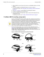
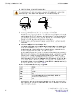
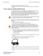
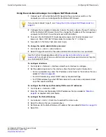
Open the handles to their fully open positions.

6

Carefully guide the board into the chassis using the rails in the slot.

Insert the board by applying moderate force to the front faceplate (not the handles) to 
slide the board into the slot. The board should glide smoothly into the chassis slot. If 
you encounter any resistance while sliding the board in, the board could be aligned 
incorrectly. Pull the board back out and try inserting it again.

7

Slide the board in until the alignment pins are inserted half way into their sockets in 
the chassis.

8

Turn both handles to their fully-closed positions.

The handles should hook into the sides of the chassis slot. Closing the handles draws 
the FortiGate-5001D board into place in the chassis slot and into full contact with the 
chassis backplane. The FortiGate-5001D front panel should be in contact with the 
chassis front panel and both handles should lock into place.

As the handles closed power is supplied to the board. If the chassis is powered on the 
IPM LED starts flashing blue. If the board is aligned correctly, inserted all the way into 
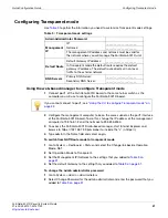
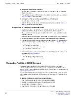
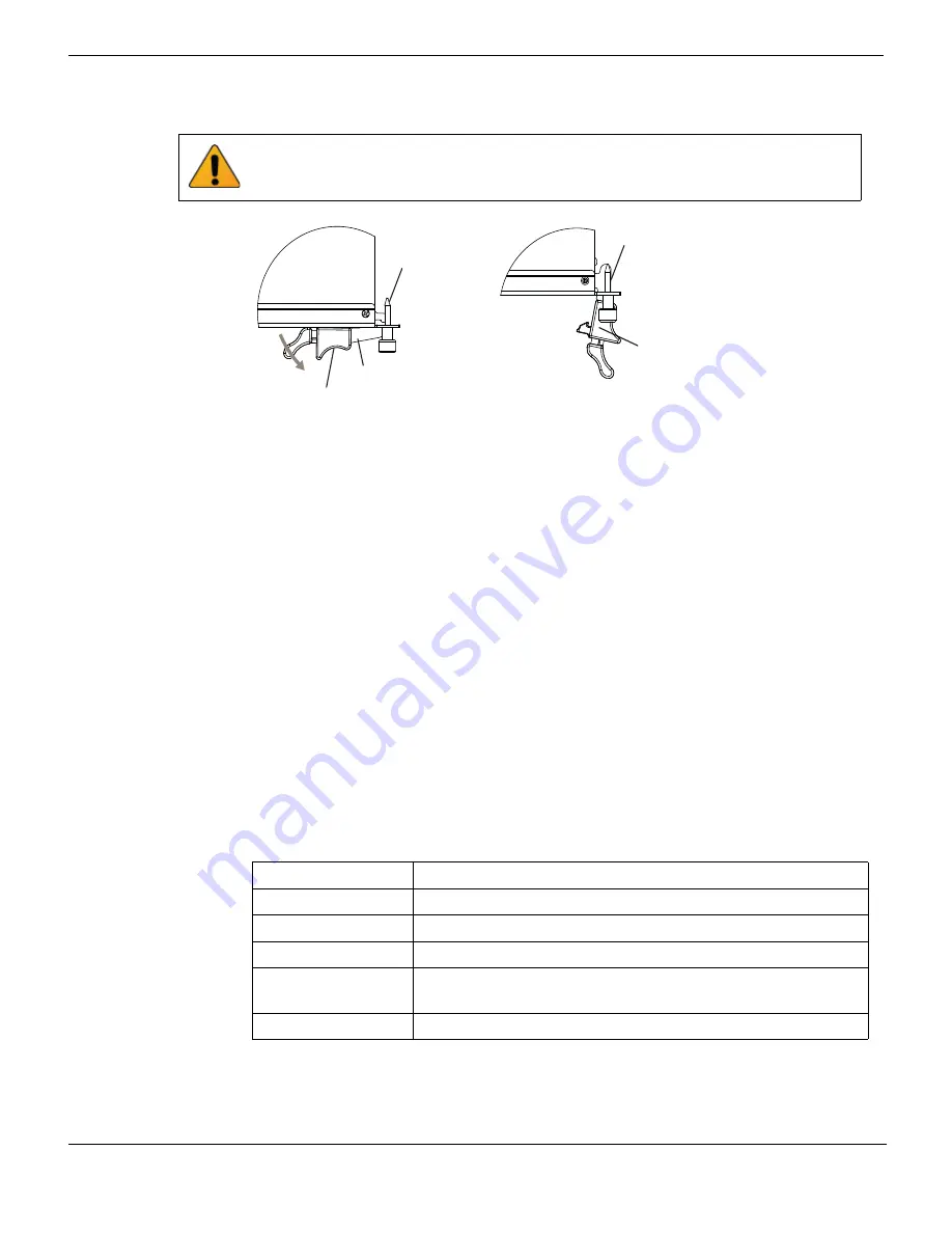
the slot, and the handles are properly closed the IPM LED flashes blue for a few 
seconds. At the same time the STATUS LED flashes green, the interface LEDs flash 
amber, and the ACC LED starts flashing green. After a few seconds the IPM LED goes 
out and the FortiGate-5001D firmware starts up. During start up the STATUS LED may 
continue to flash green. Once the board has started up and is operating correctly, the 
front panel LEDs are lit as described in 

Table 6

.

If the board has not been inserted properly the IPM LED changes to solid blue and all 
other LEDS turn off. If this occurs, open the handles, slide the board part way out, and 
repeat the insertion process.

To avoid damaging the lock, make sure you squeeze the handles fully to unlock them 
before opening. The handles should pop easily out of the board front panel.

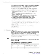
Table 6:   FortiGate-5001D normal operating LEDs

LED

State

OOS

Off

PWR

Green

STA

Off

ACC

Off (Or flashing green when the system accesses the 
FortiGate-5001D flash disk.)

IPM

Off

Handle

Alignment Pin

Open

Alignment Pin

Lock

Handle

Summary of Contents for FortiGate-5001D

Page 1: ...cent versions of this and all FortiGate 5000 series documents are available from the FortiGate 5000 page of the Fortinet Technical Documentation web site http docs fortinet com Visit https support for...

Page 2: ...includes supply connections e g power strips not only direct connections to the branch circuit Mise la terre Assurez vous que tout l quipement est mis la terre Ceci comprend les connexions d alimentat...

Page 3: ...3 Changing FortiGate 5001D SW6 switch settings 14 FortiGate 5001D mounting components 16 Inserting a FortiGate 5001D board 17 Shutting down and removing a FortiGate 5001D board 19 Power cycling a Fort...

Page 4: ...nication 33 FortiGate 5001D fabric backplane data communication 35 For more information 36 Training Services 36 Technical Documentation 36 Comments on Fortinet technical documentation 36 Customer serv...

Page 5: ...aces Use the front panel interfaces for connections to your networks and the backplane interfaces for communication across the ATCA chassis backplane The FortiGate 5001D also includes two front panel...

Page 6: ...fic on the interfaces port1 port2 port3 port4 fabirc1 and fabric2 Four CP8 content processors that accelerate IPS SSL VPN and IPsec VPN Internal 200 GByte SSD for storing log messages DLP archives his...

Page 7: ...and the connected equipment has power Flashing Green Network activity at the interface Off No link is established Fabric 1 and 2 Off Fabric backplane interface 1 or 2 fabric1 or fabric2 is connected...

Page 8: ...bps IPM Blue The FortiGate 5001D board is ready to be hot swapped removed from the chassis If the IPM light is blue and no other LEDs are lit the FortiGate 5001D board has lost power Flashing Blue The...

Page 9: ...slots 1 and 2 For information about FortiSwitch and FortiController 5000 series boards see the FortiGate 5000 page of the Fortinet Technical Documentation website Fabric backplane communication The Fo...

Page 10: ...g load is removed from the CPU The NP6 processor can also handle some CPU intensive tasks like IPsec VPN encryption decryption Because of the integrated switch fabric all sessions are fast pathed and...

Page 11: ...re CRT support Primarily checking for RSA key generation Handshake accelerator with automatic key material generation Random Number generator compliance with ANSI X9 31 Sub public key engine PKCE to s...

Page 12: ...Splitting the FortiGate 5001D front panel port1 and port2 interfaces FortiGate 5001D security system FortiGate 5001D Security System Guide 12 01 500 0242101 20151109 http docs fortinet com...

Page 13: ...You can install the QSFP transceivers before or after inserting the FortiGate 5001D board into a chassis You must install SR SFP transceivers for normal operation of the FortiGate 5001D front panel p...

Page 14: ...es chassis The top of the FortiGate 5001D board is covered with a metal panel The printed circuit board is under the metal panel SW6 is located on the printed circuit board and is accessible from the...

Page 15: ...electrostatic discharge ESD preventive wrist strap with connection cord Table 5 FortiGate 5001D SW6 settings Chassis Correct SW6 Setting Result of wrong jumper setting FortiGate 5140B or 5060 or a ATC...

Page 16: ...o place in the slot When locked into place and positioned correctly the board front panel is flush with the chassis front panel The board is also connected to the chassis backplane To position the boa...

Page 17: ...are hot swappable The procedure for inserting a FortiGate 5001D board into a chassis slot is the same whether or not the chassis is powered on To insert a FortiGate 5001D board into a chassis slot To...

Page 18: ...ould lock into place As the handles closed power is supplied to the board If the chassis is powered on the IPM LED starts flashing blue If the board is aligned correctly inserted all the way into the...

Page 19: ...ate 5001D board For example From the web based manager go to System Status and from the Unit Operation widget select Shutdown and then select OK From the CLI enter execute shutdown 2 Attach the ESD wr...

Page 20: ...open the handles with moderate pressure to eject the board from the chassis Pivoting the handles turns off the microswitch turns off all LEDs and ejects the board from the chassis slot 9 Pull the boar...

Page 21: ...e 5001D board installed An electrostatic discharge ESD preventive wrist strap with connection cord 1 Shut down the operating system running on the FortiGate 5001D board For example From the web based...

Page 22: ...s If you are operating a FortiGate 5000 series chassis you can power down and then restart the chassis without removing FortiGate 5000 series components All chassis Firmware problem If the FortiGate 5...

Page 23: ...in some cases you have to set these interface speeds to 40000full if the cluster is installed in a FortiGate 5144C chassis or 10000full if the cluster is installed in a chassis with a 10 gbyte backpl...

Page 24: ...Troubleshooting Hardware installation FortiGate 5001D Security System Guide 24 01 500 0242101 20151109 http docs fortinet com...

Page 25: ...ct to receive Fortinet customer services such as product updates and customer support You must also register your product for FortiGuard services such as FortiGuard Antivirus and Intrusion Prevention...

Page 26: ...oute mode Transparent mode In Transparent mode the FortiGate 5001D security system is invisible to the network All of the FortiGate 5001D interfaces are connected to different segments of the same net...

Page 27: ...et connection between the FortiGate 5001D board and management computer Internet Explorer 6 0 or higher on the management computer Command Line Interface CLI The CLI is a full featured management tool...

Page 28: ...1 IP Netmask 192 168 1 99 24 mgmt2 IP Netmask 192 168 100 99 24 Default route Gateway 192 168 100 1 Device mgmt2 Primary DNS Server 208 91 112 53 Secondary DNS Server 208 91 112 52 At any time during...

Page 29: ...o System Network Interface and edit each interface to configure 2 Set the addressing mode for the interface See the online help for information For manual addressing enter the IP address and netmask f...

Page 30: ...edit admin set password password end 5 Configure the mgmt1 port1 and port1 interfaces to the settings that you added to Table 8 on page 28 config system interface edit mgmt1 set ip intf_ip netmask_ip...

Page 31: ...System Dashboard Status and select the Change link beside Operation Mode NAT 2 Set Operation Mode to Transparent 3 Set the Management IP Netmask to the settings that you added to Table 9 on page 31 4...

Page 32: ...twice no password required 4 Change from NAT Route mode to Transparent mode Configure the Management IP address and default gateway to the settings that you added to Table 9 on page 31 config system s...

Page 33: ...TFTP server You can use the following command to ping the computer running the TFTP server For example if the IP address of the TFTP server is 192 168 1 168 execute ping 192 168 1 168 5 Enter the foll...

Page 34: ...ons Guide and the FortiSwitch 5000 Series CLI Reference To enable base backplane data communication from the FortiGate 5001D web based manager From the FortiGate 5001D web based manager use the follow...

Page 35: ...stem Network Interface 2 Select Show backplane interfaces The fabric1 fabric2 base1 and base2 backplane interfaces now appear in all Interface lists You can now configure the fabric backplane interfac...

Page 36: ...ticles examples FAQs technical notes and more Visit the Fortinet Knowledge Base at http kb fortinet com Comments on Fortinet technical documentation Send information about any errors or omissions in t...

Page 37: ...ortinet enters a binding written contract signed by Fortinet s General Counsel with a purchaser that expressly warrants that the identified product will perform according to certain expressly identifi...

Page 38: ...residential area is likely to cause harmful interference in which case the user will be required to correct the interference at his own expense WARNING Any changes or modifications to this product no...

Reviews: