Using the chassis system event log (SEL)
Using the shelf manager CLI
FortiGate-5060 Chassis Guide
64
01-400-129494-20110912
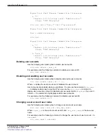
00b0 c1
Some releases of the Shelf Manager allow selecting between three PET formats. The
values are defined as follows:
0 = the default IPMI format defined by IPMI Platform Event Trap Format v1.0
specification.
1 = plain text format; all the event details are sent as plain ASCII text in a single
variable.
2 = multi-variable format; each event field is encoded as a separate variable
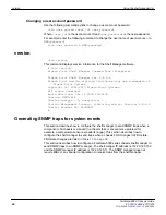
Removing and inserting a fan tray
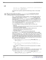
You could also test traps by removing and then inserting fan tray 1. When removed, it
caused a state change (M4 -> M7) and a SNMP trap sent with byte 4 of specific trap field
= 07. Byte 29 of variable binding fields was equal to 06 = FRU 4 hot swap sensor.
# clia fru 20 4
20: FRU # 4
Entity: (0x1e, 0x61)
Hot Swap State: M4 (Active), Previous: M3 (Activation In
Process), Last State Change
Cause: Normal State Change (0x0)
Device ID String: "Fan Tray 1"
# clia sensor 20 6
20: LUN: 0, Sensor # 6 ("FRU 4 HOT_SWAP")
Type: Discrete (0x6f), "Hot Swap" (0xf0)
Belongs to entity: (0x1e, 97) [FRU # 4]
When inserted, there are 4 state changes and 4 SNMP traps sent.
Using the chassis system event log (SEL)
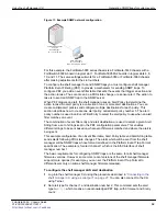
This section document describes the components that make up a FortiGate-5000-series
chassis, describes how to read the system event logs stored on the shelf manager and
record all system events. For more information about the SEL, see
Before you begin
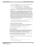
Before going further in this section, you should log into your active shelf manager and
enter the following commands. This will be a good reference for what you physically have
in your system and will help with understanding other areas of this section.
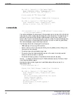
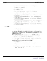
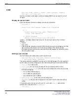
# clia ipmc
# clia fru
# clia sensor
# clia sel
See
“Example IPMC log output” on page 67
,
“Example FRU log output” on page 68
and
“Example sensor log output” on page 69
Chassis Design Background
All the devices in an ATCA chassis are controlled and monitored through an IPMC. Each
shelf manager and all ATCA boards have their own physical IPMC chip and are assigned
an IPMC address. Their unique address is assigned based on what chassis slot they are
physically inserted into. Additionally, there is a reserved logical chassis IPMC address of
20 hex which is created and controlled by the active shelf manager.

