Using the shelf manager CLI
Using the chassis system event log (SEL)
FortiGate-5060 Chassis Guide
01-400-129494-20110912
65
•
• Shelf Manager slot 1 = IPMC address 10 hex
• Shelf Manager slot 2 = IPMC address 12 hex
• ATCA slot 1 = IPMC address 82 hex
• ATCA slot 14 = IPMC address 9C hex
• Logical IPMC from Active Shelf Manager = IPMC address 20 hex
The IPMC connects to and monitors the readings on various sensors located on devices in
the system. These devices are typically called FRUs. The term FRU generally refers to
any removable or field replaceable component, but in a more technical view can be any
unique device in the system even if it is not removable, such as a backplane.
• FortiGate-5001A in ATCA slot 1 = (IPMC 82) FRU 0
• Shelf Manager in SM slot 1 = (IPMC 10) FRU 0
• Shelf Manager in SM slot 2 = (IPMC 12) FRU 0
All the other FRU devices that make up a chassis are referenced through the logical IPMC
address 20.
• SAP (Shelf Alarm Panel) = (IPMC 20) FRU 8
• Fan tray 1 = (IPMC 20) FRU 4
• Fan tray 2 = (IPMC 20) FRU 5
• PEM A (Power Entry Module A) = (IPMC 20) FRU 6
See
“IPMB addresses, logical and physical slot numbers, and FRU ids” on page 30
complete list.
The sensors on the various FRUs report back to their respective IPMC. Sensors
connected to chassis FRU devices like the fan trays or power entry modules can report
back their sensor readings through either IPMC 10h/12h or through the Logical 20h
address, but not both. Sensors on ATCA boards always report back through their
respective blade IPMC address.
• Backup battery voltage sensor on SM1 = (IPMC 10) Sensor #6
• RPM of fan 1 of 2 in Fan Tray 0 = (IPMC 10) Sensor #7
• RPM of fan 2 of 2 in Fan Tray 2 = (IPMC 10) Sensor #14
• Physical presence of Fan Tray 2 = (IPMC 20) Sensor #14
• Chassis center exhaust temperature = (IPMC 20) sensor #120
• Slot 1 FG-5005FA2 ambient incoming temp = (IPMC 82) Sensor #12
You can check the IPMB bus state (if the bus it in failure, nothing works). A backup bus
exists so there are 2 IPMB buses handled by the active shelf manager (and not one bus
per shelf manager). Use the following command to check the IPMB bus state:
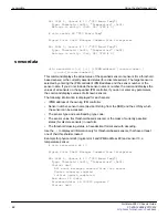
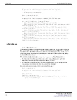
# clia getipmbstate 10
Pigeon Point Shelf Manager Command Line Interpreter
10: Link: 0, LUN: 0, Sensor # 1 ("IPMB LINK")
Bus Status: 0x8 (IPMB-A Enabled, IPMB-B Enabled)
IPMB A State: 0x08 (LocalControl, No failure)
IPMB B State: 0x08 (LocalControl, No failure)
Alarm LEDs
Alarms are also reported by LEDs on the chassis shelf alarm panel or shelf manager.
FRUs such as fan trays and PEMs also have alarm LEDs. So for example, if a FAN goes
into an alarm state, the alarm LED located on the FAN turns to RED.


