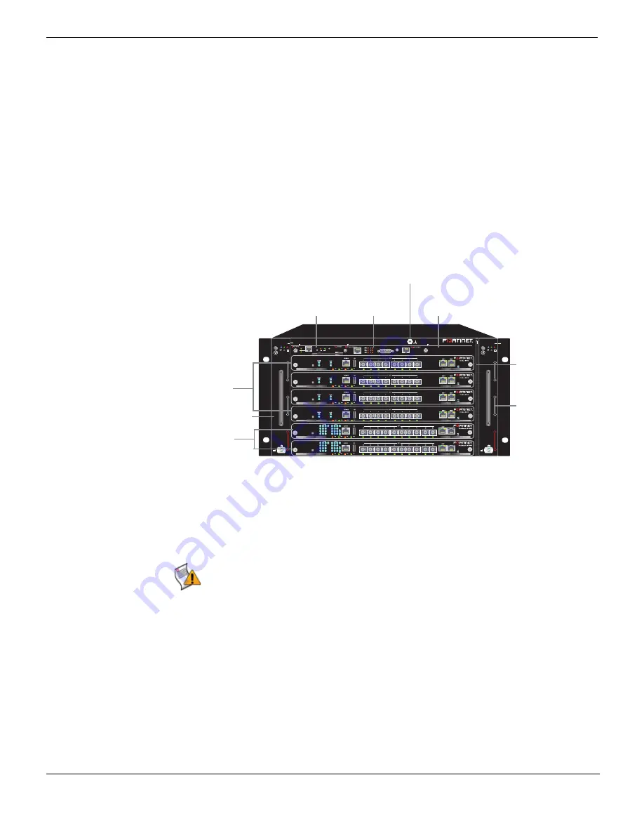
FortiGate-5060 front panel
FortiGate-5060 chassis
FortiGate-5060 Chassis Guide
8
01-400-129494-20110912
FortiGate-5060 front panel
shows the front of a FortiGate-5060 chassis. Two FortiSwitch-5003B boards are
installed in slots 1 and 2. Four FortiGate-5001B boards are installed in slots 3, 4, 5, and 6.
The FortiGate-5060 primary Shelf Manager and the Shelf Alarm Panel (SAP) are also
visible. The factory installed shelf alarm panel displays alarms, provides a telco alarm
interface, and also provides serial connections to the shelf managers. The factory installed
primary shelf manager provides power allocation, cooling, alarms, and shelf status for the
FortiGate-5060 chassis. You can also install a secondary shelf manager as a backup for
the primary shelf manager. For more information about these components, see
“FortiGate-5060 shelf alarm panel” on page 12
“FortiGate-5060 shelf managers” on
.
Figure 1: FortiGate-5060 front panel with FortiGate-5001B and FortiSwitch-5003B boards
installed
Also visible on the front of the FortiGate-5060 chassis:
• The location of the two hot-swappable FortiGate-5060 cooling fan trays.
• The location of the front-replaceable air filter.
• The Electrostatic discharge (ESD) socket, used for connecting an ESD wrist band
when working with the chassis.
FAN TRAY
1
2
3
4
5
6
FAN TRAY
1
2
3
4
5
6
FIL
T
ER
T
O
P
1
2
5060SAP
SERIAL
1
SERIAL
2
RESET
ALARM
10/100
link/Act
ETH0 Service
RESET
ST
AT
US
Hot Swap
link/Act
ETH0
ETH1
10/100
5000SM
SM1
SAP
SM2
FortiGate 5060
1
1
1
1
Hot-swappable
cooling fan tray 2
Front-replacable
air filter
Hot-swappable
cooling fan tray 1
FortiGate-5001B
boards, slots 3,
4, 5, and 6
FortiSwitch-5003B
boards
slots 1 and 2
Primary
Shelf Manager
(SM 1)
Secondary
Shelf Manager
(SM 2) Slot Cover
Shelf Alarm
Panel (SAP)
ESD socket
Caution:
Do not operate the FortiGate-5060 chassis with open slots on the front panel. For
optimum cooling performance and safety, the chassis slots must contain a FortiGate-5000
series board or an air baffle slot filler. For the same reason, both cooling fan trays and the
air filter should be installed while operating the chassis. As well both PEMs must be
installed in the back of the chassis.


