background image

FortiGate-5060 shelf alarm panel

FortiGate-5060 chassis

 FortiGate-5060   Chassis Guide 

14

01-400-129494-20110912

http://docs.fortinet.com/

 • 

Feedback

Figure 5: Connections between the shelf managers and the shelf alarm panel

Shelf alarm panel telco alarms

The shelf alarm panel telco alarm interface relay circuits are capable of carrying 60 VDC 
or 1 A with a max. rating of 30 VA. The shelf alarm panel accepts timed pulse inputs for 
clearing minor and major alarm states. Reset is accomplished by asserting a voltage 
differential from 3.3 V to 48 V for between 200 and 300 ms. The acceptance voltage range 
is from 0 to 48 VDC continuous (handles up to 60 VDC at a 50% duty cycle). The current 
drawn by a reset input does not exceed 12 mA.
The alarm LED reset button activates the alarm cutoff (ACO) state for major, minor, and 
user-defined alarms. You cannot reset critical alarms with the alarm LED reset button. 
When the ACO state is activated, active alarm LEDs blink and all of the alarm relays are 
deactivated. The alarm reset button activates the ACO state but does not clear the alarm 
completely. 

Figure 6: The telco alarm connector (DB-15 male)

5000SAP

SERIAL

1

SERIAL

2

RESET

ALARM 

Primary Shelf Manager (Right)

I²C-Switch

PCA9545

Buffer

LTC4300

ShMM-500

el

b

a

n

E

yl

n

O-

r

et

s

a

M

s

u

b-

C²I

e

c

af

r

et

nI

el

o

s

n

o

C

l

air

e

S

Secondary Shelf Manager (Left)

I²C-Switch

PCA9545

el

b

a

n

E

yl

n

O-

r

et

s

a

M

s

u

b-

C²I

e

c

af

r

et

nI

el

o

s

n

o

C

l

air

e

S

Buffer

LTC4300

ShMM-500

0

H

C

3

H

C

0

H

C

3

H

C

1

9

15

8

Summary of Contents for FortiGate-5060

Page 1: ...60 Chassis Guide describes FortiGate 5060 hardware features and how to install the FortiGate 5060 chassis The most recent versions of this and all FortiGate 5000 series documents are available from th...

Page 2: ...ion by wearing an anti static wrist strap and attaching it to an available ESD connector such as the ESD sockets provided on FortiGate 5000 series chassis Make sure all FortiGate 5000 series component...

Page 3: ...r 15 Cooling fan trays 16 Power connection and configuration 17 About data center DC power 17 Connecting the FortiGate 5060 chassis to DC power and data center ground 17 Connecting a FortiGate 5060 PE...

Page 4: ...ensors that are outside of established thresholds 31 Display sensor data for a FRU 31 Display the FRU information for a FRU 31 Change the speed for a fan tray 31 Display the contents of the system eve...

Page 5: ...Changing a user account password 58 version 58 Generating SNMP traps for system events 58 SNMP trap details 62 Removing and inserting a fan tray 64 Using the chassis system event log SEL 64 Before you...

Page 6: ...Contents FortiGate 5060 Chassis Guide 6 01 400 129494 20110912 http docs fortinet com Feedback...

Page 7: ...f the boards installed in a FortiGate 5060 chassis can be operating in a FortiGate HA cluster and some can be operating as standalone FortiGate units You can also operate multiple HA clusters and stan...

Page 8: ...ortiSwitch 5003B boards installed Also visible on the front of the FortiGate 5060 chassis The location of the two hot swappable FortiGate 5060 cooling fan trays The location of the front replaceable a...

Page 9: ...B to a DC power source Figure 2 FortiGate 5060 chassis back panel shows PEM B connected to DC power source The back panel includes the FortiGate 5060 chassis ground connector which must be connected t...

Page 10: ...tive shelf manager fails or is removed the standby shelf manager takes over all shelf manager functions The FortiGate 5060 shelf managers control chassis power allocation monitor chassis operating par...

Page 11: ...ased set of commands that can be accessed directly or through a higher level management application or a script Using the CLI you can access information about the current state of the chassis includin...

Page 12: ...Gate 5060 shelf alarm panel The FortiGate 5060 shelf alarm panel SAP located at the top of the FortiGate 5060 front panel provides LED indicators of FortiGate 5060 alarms a telco alarm connector an al...

Page 13: ...icates a minor alarm Blinking Amber Alarm cutoff ACO activated by pressing the alarm LED reset button USER3 USER2 USER1 Off Normal operation Amber Indicates a user definable alarm Blinking Amber Alarm...

Page 14: ...duty cycle The current drawn by a reset input does not exceed 12 mA The alarm LED reset button activates the alarm cutoff ACO state for major minor and user defined alarms You cannot reset critical al...

Page 15: ...pected regularly If dirty or damaged the filter should be disposed of and replaced The air filter can be removed using the air filter handle on the front of the FortiGate 5060 chassis To install a new...

Page 16: ...led in the FortiGate 5060 chassis Fan speeds are monitored by a tachometer signal sent from the cooling fan trays to the shelf manager The shelf manager regulates the fan speed by adjusting the DC vol...

Page 17: ...quipped with a 48VDC power system fed from a 30A listed circuit breaker that provides power to existing networking or telecom equipment The FortiGate 5060 chassis is designed to be connected directly...

Page 18: ...tions not supplied with the chassis If you are connecting both PEMs the 48VDC and RTN terminals on PEM A and PEM B must be wired symmetrically This means that the connections must be the same to both...

Page 19: ...60 PEM labeled 48V 60 V the lower connectors on the PEM Connect two red RTN return wires from data center RTN to the connectors on the FortiGate 5060 PEM labeled RTN the upper connectors on the PEM 5...

Page 20: ...power converter shelf with hot swappable power supplies to convert AC power to DC power FortiGate power converter shelves and power supplies are not supplied with the FortiGate 5060 chassis and must b...

Page 21: ...trays should be lit As well the Status LED on the FortiGate 5060 shelf manager front panel should be lit see Figure 3 on page 11 None of the LEDs on the shelf alarm panel SAP should be lit see Figure...

Page 22: ...Turning on FortiGate 5060 chassis power Power connection and configuration FortiGate 5060 Chassis Guide 22 01 400 129494 20110912 http docs fortinet com Feedback...

Page 23: ...t exceed the manufacturer s maximum rated ambient temperature Air flow For rack installation make sure that the amount of air flow required for safe operation of the FortiGate 5060 chassis is not comp...

Page 24: ...c backplane results in three connections between the FortiSwitch 5003A boards which could also result in FortiGate boards installed in the chassis and operating in Transparent mode to have multiple co...

Page 25: ...1 or slot 2 provide base backplane switching for all of the FortiGate 5000 series boards installed in the chassis Base backplane switching is usually used for HA heartbeat communication between FortiG...

Page 26: ...Using FortiSwitch 5003A boards for backplane communication FortiGate 5060 hardware procedures FortiGate 5060 Chassis Guide 26 01 400 129494 20110912 http docs fortinet com Feedback...

Page 27: ...on two redundant physical buses The shelf manager CLI can be used to communicate with the intelligent management controllers of the shelf with boards and with the Shelf Manager itself The CLI is an I...

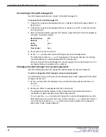
Page 28: ...ccount When you log into the shelf manager CLI you are logging into a Linux shell as root You can begin entering commands at the prompt Changing the shelf manager root account password Use the followi...

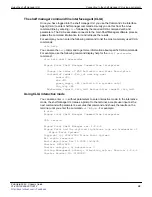
Page 29: ...ommand clia help shelf pwrreorder Pigeon Point Shelf Manager Command Line Interpreter Change the order of FRU Activation and Power Descriptors instead of addr fru_id user may use board N shm N power_s...

Page 30: ...oard is installed in a slot the slot will have one FRU with an ID of FRU 0 However if a FortiGate 5001A board is installed in a slot with an AMC module this slot has two FRUs FRU 0 and FRU 1 For examp...

Page 31: ...p ip_address channel is the shelf manager channel and can be 1 or 2 ip_address is the new IP address in dotted decimal notation For example clia setlanconfig 1 ip 192 168 0 2 Display the shelf manager...

Page 32: ...ress Manually Configured 0x01 MAC Address 00 50 c2 3f f0 9a Subnet Mask 255 255 255 0 IPv4 Header Parameters 0x40 0x40 0x10 Primary RMCP Port Number 0x026f Secondary RMCP Port Number 0x0298 BMC genera...

Page 33: ...in hexadecimal defined in the IPMI specification Example of sensor type 01 for temperature sensor 02 for voltage sensor C0 FF for OEM reserved sensors F0 is the hot swap sensor and F1 is the IPMB link...

Page 34: ...ables the ability to clear the critical alarm condition without the alarm cutoff button Default is FALSE ALLOW_CLEARING_CRITICAL_ALARM FALSE If you change ALLOW_CLEARING_CRITICAL_ALARM to TRUE you can...

Page 35: ...nd easier to use when boards may not include an IPM controller and therefore are not easily addressable using the IPMB address FRU device ID pair Viewing information about a board Enter the following...

Page 36: ...ll fan FRUs controlled by the IPM controller at the specified address If IPMB_address is also omitted the command displays information about all fan FRUs known to the shelf manager The command display...

Page 37: ...Hot Swap State M4 Active Previous M3 Activation In Process Last State Change Cause Normal State Change 0x0 Device ID String PPS BMC 20 FRU 1 Entity 0xf2 0x60 Hot Swap State M4 Active Previous M3 Acti...

Page 38: ...ress that refers to a physical slot to display information similar to that displayed by the clia board command see board on page 35 For example to display information about the board in physical slot...

Page 39: ...t Tag 0000000000000001 FRU Programmer File ID 21990024AABIN bin Custom Product Info Multi Record Area Record Type 0xc0 OEM Defined Record Version 2 Nothing is known about this PPS record 0x01 Record T...

Page 40: ...a configuration parameter Table 11 lists some commonly used parameter_names and parameter_numbers Displaying all configuration parameters for a channel If you do not include a parameter_name or param...

Page 41: ...Shelf Manager Command Line Interpreter Subnet Mask 255 255 255 0 The following command displays the default gateway IP address associated with channel 1 clia getlanconfig 1 dft_gw_ip Pigeon Point Shel...

Page 42: ...w Data 0xb3 Processed data 1 754200 Volts 88 LUN 0 Sensor 5 CPU2 Voltage Type Threshold 0x01 Voltage 0x02 Lower Non Critical Threshold Raw Data 0x6c Processed data 1 058400 Volts Lower Critical Thresh...

Page 43: ...0600 Volts Upper Non Critical Threshold Raw Data 0xde Processed data 2 708400 Volts Upper Critical Threshold Raw Data 0xe6 Processed data 2 806000 Volts Upper Non Recoverable Threshold Raw Data 0xee P...

Page 44: ...w Data 0x85 Processed data 1 303400 Volts Upper Non Recoverable Threshold Raw Data 0x8a Processed data 1 352400 Volts 88 LUN 0 Sensor 12 Incoming Air Flo Type Threshold 0x01 Temperature 0x01 Upper Non...

Page 45: ...oint Shelf Manager Command Line Interpreter 88 LUN 0 Sensor 13 CPU Board Temp Type Threshold 0x01 Temperature 0x01 Upper Non Critical Threshold Raw Data 0x4b Processed data 75 000000 degrees C Upper C...

Page 46: ...ile name frudataw s d p l addr fru id file name frudataw s d p l c addr fru id fruinfo addr fru_id getbootdev addr fru id amc addr getconfigparam parameter name getfanlevel addr fru_id getfanpolicy ad...

Page 47: ...ENABLE DISABLE timeout s addr site_type fru_id site_n umber setfruledstate addr fru_id LedId ALL LedOp tail LedColor setfunctionpolicy EnableDisableMask NetFn CMD channel LUN sethysteresis addr lun s...

Page 48: ...name flags privilege level password user channel user id channel number flags privilege level user delete user id user enable user id 1 0 user name user id user name user passwd user id user password...

Page 49: ...el This command displays or sets the minimum fan level Under normal conditions the cooling management algorithm gradually decreases the level for the fans in the chassis while thermal conditions stay...

Page 50: ...ta in raw and processed if available formats The command sel clear clears the SEL on the specified IPM Controller at IPMB address 20h by default The v option makes the command output more user readabl...

Page 51: ...x89 0x021A Event at Aug 6 10 39 55 2009 from 0x8c 0 0 sensor 0xf1 1 event 0x6f asserted 0xA2 0x00 0x8F 0x021C Event at Aug 6 10 39 55 2009 from 0x88 0 0 sensor 0xf1 1 event 0x6f asserted 0xA3 0x00 0x8...

Page 52: ...fied IPM controller If you do not enter any parameters the command displays values of all known sensors The following information is displayed for each sensor IPMB address of the owning IPM controller...

Page 53: ...reserved If the LUN is omitted the command applies to the sensor with the specified sensor number on the lowest LUN For example if the command specifies sensor 3 without explicit LUN qualification and...

Page 54: ...ta 90 000000 degrees C shmstatus clia shmstatus v This command displays the Shelf Manager status in redundant configurations Active or Backup In verbose mode using v the command displays more informat...

Page 55: ...last state change switchover clia switchover force If a chassis has two shelf managers you can enter this command to switch the active shelf manager to running as the backup shelf manager and the back...

Page 56: ...the channel access information is the same for several channels the output displays the information for the channel number range Adding a user account Use the following command syntax to add a user a...

Page 57: ...er delete 23 Disabling and enabling user accounts Use the following command syntax to disable and enable user accounts clia user enable user_id 1 0 Where 1 enables the user account and 2 disables the...

Page 58: ...2 2009 Pigeon Point Systems All rights reserved Build date time Dec 14 2009 10 09 35 Carrier HPDL ACB Carrier subtype 0 subversion 0 Cooling Management Library libcooling_acb so Version 2 6 4 4 Carrie...

Page 59: ...se when an alert filter matches an event The combination of event filter entry and alert destination are used to select a given Alert String from a set of strings kept in the PEF configuration paramet...

Page 60: ...entries The syntax of the command is clia setpefconfig event_filter entry_number flter_configuration filter_action alert_policy_number severity IPMB_address channel sensor_type sensor_number event_typ...

Page 61: ...ddress 82 the first hub slot any channel FF is for the hot swap sensor F0 is for any sensor number FF any sensor offset FF any event type FF and any event offset FF clia setpefconfig event_filter 1 80...

Page 62: ...PEM B there are three state changes M1 M2 M3 M4 and three traps sent SNMP trap details The trap below could be sent when PEM B state changes from M4 to M6 The important trap fields are the specific t...

Page 63: ...rises 3183 1 1 1 valueType value 0 value simple 4294967295 simple string value 1 Value Hex STRING 54 FA FC B6 41 50 11 DD 00 80 00 50 C2 3F F0 9A 00 4F 13 C8 C3 75 00 00 20 20 02 20 09 00 00 A6 14 07...

Page 64: ...t Swap 0xf0 Belongs to entity 0x1e 97 FRU 4 When inserted there are 4 state changes and 4 SNMP traps sent Using the chassis system event log SEL This section document describes the components that mak...

Page 65: ...ious FRUs report back to their respective IPMC Sensors connected to chassis FRU devices like the fan trays or power entry modules can report back their sensor readings through either IPMC 10h 12h or t...

Page 66: ...x04 10 event 0x1 asserted Upper Critical Threshold 0xff Reading 0xff Where 0x018D The event ID every new event increments by 1h So the next event in the log file will be tagged with 0x018E You can use...

Page 67: ...Version 2 2 Hot Swap State M4 Active Previous M3 Activation In Process Last State Change Cause Normal State Change 0x0 20 Entity 0xf0 0x1 Maximum FRU device ID 0x10 PICMG Version 2 2 Hot Swap State M4...

Page 68: ...tate Change Cause Unknown 0xf 9c Entity 0xa0 0x60 Maximum FRU device ID 0x00 Hot Swap State M7 Communication Lost Previous M4 Active Last State Change Cause Unknown 0xf Example FRU log output clia fru...

Page 69: ...wap State M4 Active Previous M3 Activation In Process Last State Change Cause Normal State Change 0x0 Device ID String PEM A 20 FRU 7 Entity 0xa 0x61 Hot Swap State M4 Active Previous M3 Activation In...

Page 70: ...10 LUN 0 Sensor 5 I2C_PWR_B Type Threshold 0x01 Voltage 0x02 Belongs to entity 0xf0 96 FRU 0 10 LUN 0 Sensor 6 VBAT Type Threshold 0x01 Voltage 0x02 Belongs to entity 0xf0 96 FRU 0 10 LUN 0 Sensor 7...

Page 71: ...25 Belongs to entity 0xf0 96 FRU 0 10 LUN 0 Sensor 128 CPLD State Type Discrete 0x6f OEM reserved 0xde Belongs to entity 0xf0 96 FRU 0 20 LUN 0 Sensor 0 FRU 0 HOT_SWAP Type Discrete 0x6f Hot Swap 0xf0...

Page 72: ...Entity Presence 0x25 Belongs to entity 0x1e 98 FRU 5 20 LUN 0 Sensor 120 Center Exhaust Type Threshold 0x01 Temperature 0x01 Belongs to entity 0xf0 1 FRU 0 20 LUN 0 Sensor 121 Left Exhaust Type Thresh...

Page 73: ...r 163 PEM A In 2 Fused Type Discrete 0x6f Entity Presence 0x25 Belongs to entity 0xa 96 FRU 6 20 LUN 0 Sensor 164 PEM A In 1 Type Discrete 0x6f Entity Presence 0x25 Belongs to entity 0xa 96 FRU 6 20 L...

Page 74: ...Discrete 0x6f Entity Presence 0x25 Belongs to entity 0xa 97 FRU 7 20 LUN 0 Sensor 181 PEM B In 3 Fused Type Discrete 0x6f Entity Presence 0x25 Belongs to entity 0xa 97 FRU 7 20 LUN 0 Sensor 192 PEM A...

Page 75: ...FRU 3 20 LUN 0 Sensor 214 48B FT 0 Fuse Type Discrete 0x6f Entity Presence 0x25 Belongs to entity 0x1e 96 FRU 3 20 LUN 0 Sensor 215 24V FT 1 Type Discrete 0x6f Entity Presence 0x25 Belongs to entity 0...

Page 76: ...r 227 48A FT 2 Fuse Type Discrete 0x6f Entity Presence 0x25 Belongs to entity 0x1e 98 FRU 5 20 LUN 0 Sensor 228 48B FT 2 Fuse Type Discrete 0x6f Entity Presence 0x25 Belongs to entity 0x1e 98 FRU 5 86...

Page 77: ...01 Temperature 0x01 Belongs to entity 0x3 96 FRU 0 86 LUN 0 Sensor 14 CPU1 Temp Type Threshold 0x01 Temperature 0x01 Belongs to entity 0x3 96 FRU 0 Sample sections of SEL Output Shows the active shelf...

Page 78: ...erted Lower Critical Threshold 0xb3 Reading 0x99 Shows the board in ATCA slot 4 has exceeded the incoming air temperature limit 0x0080 Event at Jan 1 00 25 25 1970 from 0x8e 0 0 sensor 0x01 12 event 0...

Page 79: ...Fortinet product The documents on this CD are current at shipping time For current versions of Fortinet documentation visit the Fortinet Technical Documentation web site http docs fortinet com Fortine...

Page 80: ...out prior written permission of Fortinet Inc Trademarks Dynamic Threat Prevention System DTPS APSecure FortiASIC FortiBIOS FortiBridge FortiClient FortiGate FortiGate Unified Threat Management System...

Page 81: ...For more information Customer service and technical support FortiGate 5060 Chassis Guide 01 400 129494 20110912 81 http docs fortinet com Feedback...

Reviews: