Cooling fans, cooling air flow, and minimum clearance
FortiGate-5140B chassis
FortiGate-5140B Chassis Guide
20
01-500-156415-20151104
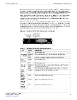
To service the fans, open the latches on either side of the fan cabinet and open the cover
by pulling it down. Access the top fans by pulling them out. Access the bottom fans by
pulling them out by their handles.
You do not need to press a hot swap switch to remove a fan. Just pull it out of the fan
cabinet. The shelf manager regulates the fan speed by adjusting the DC voltage supplied
to the fan trays.
Figure 7: Cooling air flow and required minimum air flow clearance
When installing the chassis, make sure there is enough clearance for effective cooling air
flow. See
for the minimum clearance requirements. The diagram also
shows the cooling air flow through the chassis and the location of the air filter and cooling
fans. Make sure the cooling air intake and warm air exhaust openings are not blocked by
cables or rack construction because this could result in cooling performance reduction
and possible overheating and component damage.
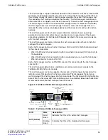
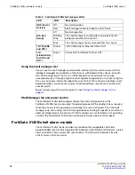
Table 5: FortiGate-5140B fan tray LEDs
LED
Description
HS (Hot Swap)
Normally off. Blinking blue indicates that the fan is starting up.
OOS (Out of
Service)
Normally off. Blinking red indicates the fan is out of service and
should be replaced.
100 mm
600 mm
600 mm
Cool air
Intake
Warm air
Exhau
s
t
60 mm
40 mm
Front
Back
Air Filter
(normal operation)
Air Filter
(Tilted down to
remove or in
s
ert)
Fan
Fan

