Power connection and configuration
Connecting a FortiGate-5140B PEM to DC power
FortiGate-5140B Chassis Guide
01-500-156415-20151104
23
Crimping guidelines
To connect the PEMs to datacenter power you should use AWG-6 or larger wires
depending on the length and the power requirements of your chassis. The ends of these
wires must be fitted with 3/4-inch double-hole lugs with insulating boot suitable the DC
cables used, such as Thomas & Betts PN 256-30695-1225. Use the following information
to crimp and prepare these wires.
Before crimping, slide rubber boot along each wire. Follow these crimping guidelines:
•
Strip the insulation from cable. Be careful not to nick cable strands which may later
result in stands breaking
•
Cable end should be clean: wire brush or clean with emery cloth if necessary. Insert
cable into connector until it stops. The insertion length must approximate the stripped
length of cable
•
Insert connector in die and compress between the markings beginning near the
tongue of the connector. Using the wrong installing die may result in a defective
connection.
•
After crimping, remove all sharp edges, flash or burrs.
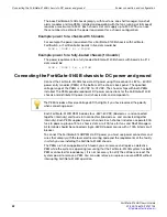
Connecting a FortiGate-5140B PEM to DC power
The following procedure describes how to connect power to a PEM. You can repeat this
procedure for both PEMs.
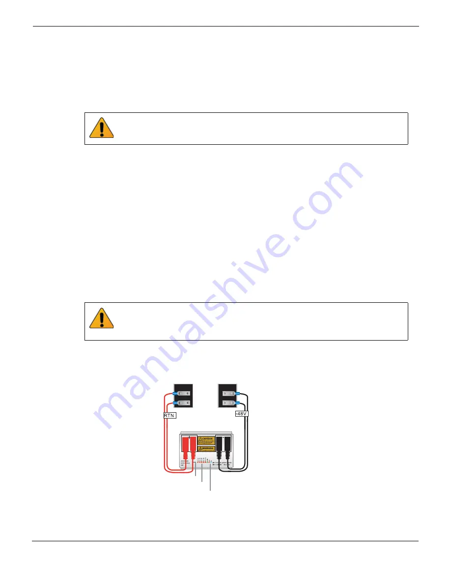
Figure 8: Connecting a FortiGate-5140B PEM to DC power
Do not crimp energized wires.
Two DC cable sets are required for each PEM connection (and all 4 terminals on each
polarity should be used). If for any reason any of the PEM terminals are not used the
unused terminals need to be covered with insulated material (or wrapped with electrical
tape) as the exposed terminals are a shock hazard.
DC Power
S
ource
-48VDC
connector
RTN (+)
red to power
s
ource RTN
DC Power
S
ource
RTN connector
-48V/-60 VDC
black to power
s
ource -48VDC
Rever
s
e Voltage LED
Fu
s
e LED
s
Active OO
S
H/
S

