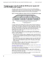
Supplying power using the FortiGate-5053B power supply shelf and PSU-5000B power supplies
Power connection and
FortiGate-5140B Chassis Guide
28
01-500-156415-20151104
Connecting a FortiGate-5140B chassis to the FortiGate-5053B power supply
shelf
To use a FortiGate-5053B power supply shelf with the FortiGate-5140B chassis you need
to make DC power connections between A FortiGate-5140B PEM and the
FortiGate-5053B power supply shelf. You also need to the connect the FortiGate-5140B
chassis and the FortiGate-5053B power supply shelf to ground.
If your configuration requires a FortiGate-5053B-LC unit you must also connect it to the
FortiGate-5140B PEM.
Connecting a FortiGate-5140B chassis to a single FortiGate-5053B power
supply shelf
The following procedure describes how to connect power to one FortiGate-5140B PEM
using the FortiGate-5053B power supply shelf. You can repeat this procedure to connect
the other PEM to a second FortiGate-5053B power supply shelf.
You need the following equipment:
•
An electrostatic discharge (ESD) preventive wrist strap with connection cord.
•
Two black AWG-6 stranded wires labelled -48V with attached Listed closed loop
double-hole lugs with insulating boot suitable for minimum AWG-6 copper wire
(supplied by Fortinet), such as Thomas & Betts PN 256-30695-1225
•
Two red AWG-6 stranded wires labelled RTN with attached Listed closed loop double-
hole lugs with insulating boot suitable for minimum AWG-6 copper wire, such as
Thomas & Betts PN 256-30695-1225.
•
A FortiGate-5053B power supply shelf containing the required number of PSU-5000B
power supplies and mounted in a rack near the FortiGate-5140B chassis.
To connect a FortiGate-5140B power input connector to a FortiGate-5053B power
supply shelf
1
Attach the ESD wrist strap to your wrist and to an ESD socket or to a bare metal
surface on the chassis or frame.
2
Make sure that the PEM, power supply shelf and DC power cable are not energized.
3
Remove the first set of nuts and lock washers from both connectors on the back of
the FortiGate-5053B power supply shelf.
4
Connect two black -48V power wires to the connectors labelled NEG on the back of
the FortiGate-5053B power supply shelf using the double-hole lug (see
Install each double-hole lug either horizontally or vertically. Do not apply torque of
more than 3.8 Nm (33.62 lbf.in).
5
Connect two black -48V power wires to the connectors labelled POS on the back of
the FortiGate-5053B power supply shelf using the double-hole lug (see
Install each double-hole lug either horizontally or vertically. Do not apply torque of
more than 3.8 Nm (33.62 lbf.in).
6
Install previously removed nuts and washers to secure the connectors.
7
Cover the connectors with the connector covers on the back of the power supply
shelf.
The FortiGate-5053B power converter shelf should not be connected to AC power until
specified in the following procedure.

