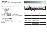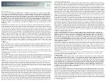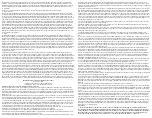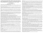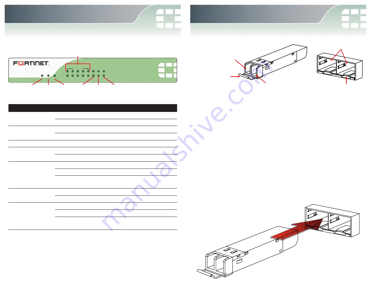
FortiGate 60C-SFP
PWR STATUS
HA
SPEED
LINK/ACT
WAN1 WAN2 WAN3
INTERNAL
1
2
3
4
5
WAN2 WAN3
WAN1
Ethernet Ports 1 to 5
Power Status
HA
6. LED Specifications
LED
State
Description
Power
Green
The unit is on.
Off
The unit is off.
Status
Flashing Green
The unit is starting up.
Green
The unit is running normally.
HA
Green
The unit is being used in an HA cluster.
Ports 1 to 5 Link/Act
Green
Port is online.
Flashing Green
Port is sending or receiving data.
Ports 1 to 5 Speed
Green
Connected at 1 Gbps.
Amber
Connected at 100 Mbps.
Off
Connected at 10 Mbps or
disconnected.
WAN1, WAN2, &
WAN3 Link/Act
Green
Port is online (link).
Flashing Green
Port is sending or receiving data.
WAN1, WAN2, &
WAN3 Speed
Green
Connected at 1 Gbps.
Amber
Connected at 100 Mbps.
Off
Connected at 10 Mbps or
disconnected.
Caution
: SFP transceiver modules are static sensitive devices. Use an ESD wrist
strap or similar grounding device when handling transceiver modules.
Caution
: Do not install or remove SFP transceiver modules while fiber-optic cables
are still attached. This can cause damage to the cables, cable connectors, and the
optical interfaces. It may also prevent the transceiver module from latching correctly
into the socket connector.
Note
: Installing and removing SFP transceiver modules can shorten their useful life.
Do not install or remove transceiver modules more than is necessary.
To install the SFP transceiver modules:
1.
Ensure that you are properly grounded.
2.
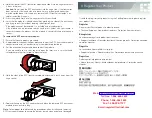
Remove the caps from SFP cage sockets on the front panel of the unit.
3.
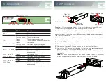
Position the SFP transceiver module in front of the cage socket opening and
ensure that the SFP transceiver module is correctly oriented.
When the module is correctly oriented, the extraction lever will be level with the
socket latch.
Note
: SFP cage socket orientation may vary. Ensure that the SFP transceiver
module is correctly oriented each time that you are inserting a module.
Extraction Lever
Transmit
Optical Bore
Receive
Optical Bore
Socket Latch
SFP Cage Sockets
7. SFP Transceivers


