background image

FortiGate-5001A   Security System Guide

6

01-30000-0438-200800801

Front panel LEDs and connectors

FortiGate-5001A security system

• Two fabric backplane gigabit interfaces (Fabric ch0 and Fabric CH1 on the 

front panel and fabric1 and fabric2 in the firmware) for data communications 
across the FortiGate-5000 chassis backplane. The fabric backplane gigabit 
interfaces can also be used for data communications across the FortiGate-
5000 chassis backplane if combined with a board that supports backplane 
fabric switching. The fabric backplane is also reserved for future 10 gigabit 
operation. 

• Dual-width AMC opening.
• RJ-45 RS-232 serial console connection.
• 2 USB connectors.
• Mounting hardware.
• LED status indicators.

Front panel LEDs and connectors

From the FortiGate-5001A font panel you can view the status of the front panel 
LEDs to verify that the board is functioning normally. You also connect the 
FortiGate-5001A board to your network through the front panel 10/100/1000 
ethernet connectors. The front panel also includes the RJ-45 console port for 
connecting to the FortiOS CLI and two USB ports. The USB ports can be used 
with any USB key for backing up and restoring configuration files. For information 
about using the using a USB key with a FortiGate unit, see the 

FortiGate-5000 

Series Firmware and FortiUSB Guide

.

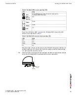
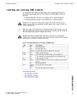
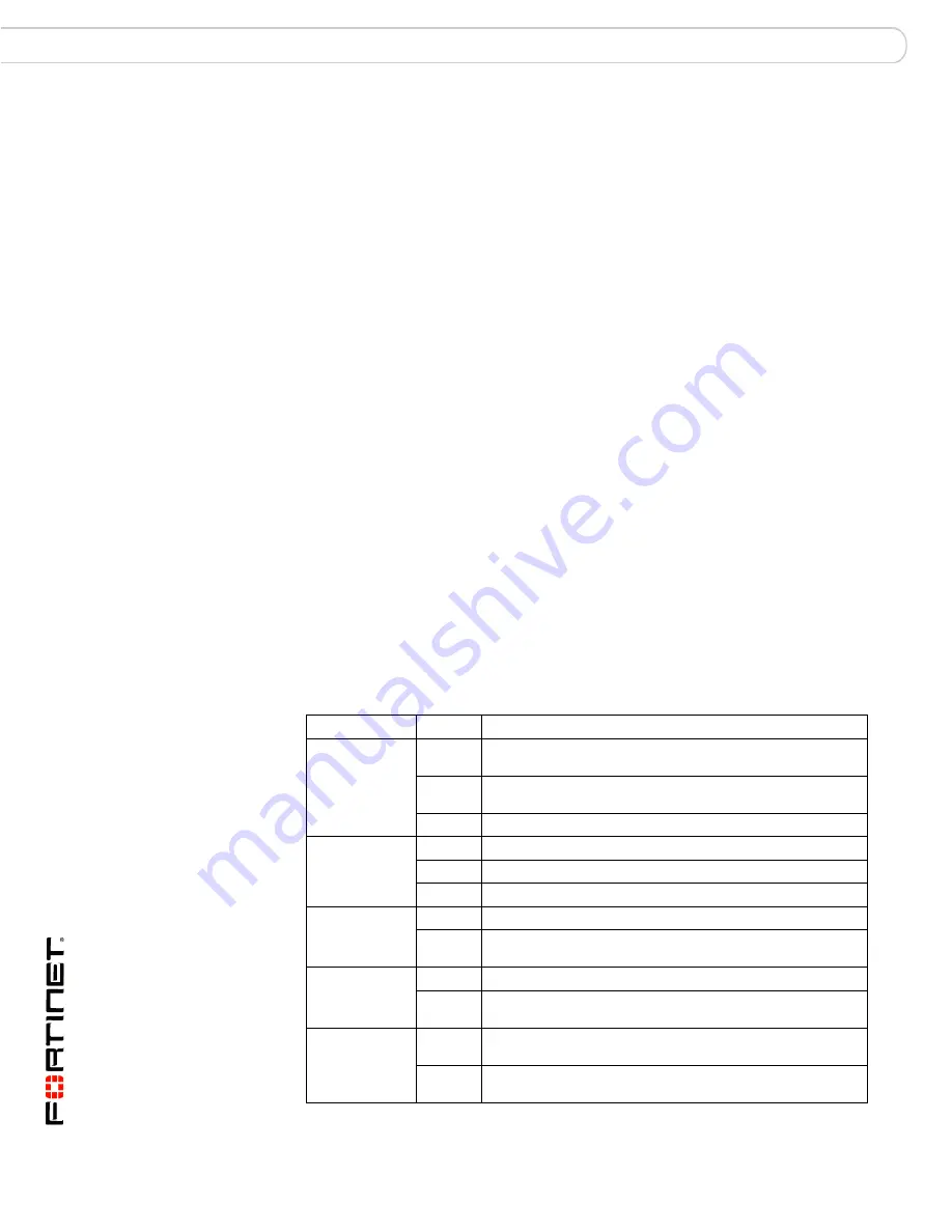
LEDs

Table 1

 lists and describes the FortiGate-5001A LEDs.

Table 1: FortiGate-5001A LEDs 

LED

State

Description

1, 2 
(Left LED)

Green

The correct cable is connected to the interface and the 

connected equipment has power.

Flashing 

Green

Network activity at the interface.

Off

No link is established.

1, 2 
(Right LED)

Green

Connection at 1 Gbps.

Amber

Connection at 100 Mbps.

Off

Connection at 10 Mbps.

Base CH0

Green

Base backplane interface 0 (base1) is connected at 1 Gbps.

Flashing 

Green

Network activity at base backplane interface 0.

Base CH1

Green

Base backplane interface 1 (base2) is connected at 1 Gbps.

Flashing 

Green

Network activity at base backplane interface 1.

Fabric CH0

Green

Fabric backplane interface 0 (fabric1) is connected at 1 

Gbps.

Flashing 

Green

Network activity at fabric backplane interface 0.

Summary of Contents for FortiGate FortiGate-5001A

Page 1: ...5001A board in a FortiGate 5000 series chassis and how to configure the FortiGate 5001A security system for your network The most recent versions of this and all FortiGate 5000 series documents are a...

Page 2: ...assembly the operating ambient temperature of the rack environment may be greater than room ambient Make sure the operating ambient temperature does not exceed the manufacturer s maximum rated ambient...

Page 3: ...talling and removing AMC modules 19 Inserting AMC slot fillers 20 Inserting AMC modules 20 Removing AMC modules 21 Troubleshooting 22 FortiGate 5001A does not start up 22 FortiGate 5001A status LED is...

Page 4: ...ransparent mode 32 Upgrading FortiGate 5001A firmware 33 FortiGate 5001A base backplane data communication 34 Powering off the FortiGate 5001A board 36 For more information 37 Fortinet documentation 3...

Page 5: ...ADM FB8 in the AMC opening The FortiGate ADM XB2 adds two accelerated 10 gigabit interfaces to the FortiGate 5001A board and the FortiGate ADM FB8 adds 8 accelerated 1 gigabit interfaces You can also...

Page 6: ...10 100 1000 ethernet connectors The front panel also includes the RJ 45 console port for connecting to the FortiOS CLI and two USB ports The USB ports can be used with any USB key for backing up and r...

Page 7: ...also flash very briefly during normal startup Power Green The FortiGate 5001A board is powered on Status Green The FortiGate 5001A board is powered on Flashing Green The FortiGate 5001A is starting up...

Page 8: ...chassis see the FortiGate 5000 Base Backplane Communication Guide For information about the FortiSwitch 5003 board see the FortiSwitch 5003 Guide Fabric backplane gigabit communication The FortiGate...

Page 9: ...ch as the FortiGate ADM XB2 or the FortiGate ADM FB8 This section describes Changing FortiGate 5001A SW11 switch settings FortiGate 5001A mounting components Inserting a FortiGate 5001A board Removing...

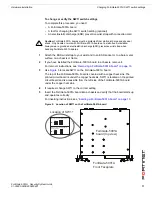
Page 10: ...5020 chassis or a chassis that does not contain an operating shelf manager you must change the SW11 switch setting as shown in Figure 4 Figure 4 FortiGate 5020 setting for SW11 standalone mode In all...

Page 11: ...s under the copper heat sink SW11 is located on the printed circuit board and is accessible from the left side of the FortiGate 5001A board under the copper heat sink 4 If required change SW11 to the...

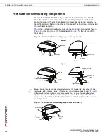
Page 12: ...nt panel Figure 6 FortiGate 5001A mounting components right handle Figure 7 FortiGate 5001A mounting components left handle Closed Open Alignment Pin Retention Screw Lock Handle Alignment Pin Retentio...

Page 13: ...d to make sure that the handles are properly locked Only then will the FortiGate 5001A board power on and start up correctly FortiGate 5001A boards are hot swappable The procedure for inserting a Fort...

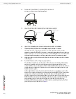
Page 14: ...9 Turn both handles to their fully closed positions The handles should hook into the sides of the chassis slot Closing the handles draws the FortiGate 5001A board into place in the chassis slot and i...

Page 15: ...s open the handles slide the board part way out and repeat the insertion process 10 Once the board is inserted correctly fully tighten the left and right retention screws to lock the FortiGate 5001A b...

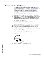
Page 16: ...ESD socket or to a bare metal surface on the chassis or frame 2 Disconnect all cables from the FortiGate 5001A board including all network cables the console cable and any USB cables or keys 3 Fully...

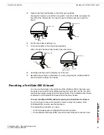
Page 17: ...outside of a chassis Resetting a FortiGate 5001A board You can use the handle on the right side of the FortiGate 5001A board to cycle the power and reset the board without ejecting the board from its...

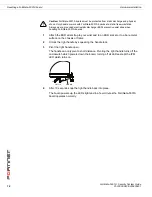
Page 18: ...he right handle turns off the microswitch which powers down the board turning off all LEDs except the IPM LED which turns on 4 After 10 seconds snap the right handle back into place The board powers u...

Page 19: ...t handle blocks the AMC opening You must eject the FortiGate 5001A board from its chassis slot and completely open the left handle before inserting or removing AMC modules or slot fillers Caution Beca...

Page 20: ...try inserting it again 6 Press the latch in the slot filler front panel to lock in the slot filler Inserting AMC modules The following steps describe how to install an AMC module into your FortiGate 5...

Page 21: ...moothly into the opening If you encounter any resistance while sliding the module in the module could be aligned incorrectly Pull the module back out and try inserting it again 9 Press the latch on th...

Page 22: ...FortiGate 5001A board for starting up correctly All chassis handles not fully closed If the handles are damaged or positioned incorrectly the FortiGate 5001A board will not start up Make sure the hand...

Page 23: ...r assistance FortiGate AMC modules not detected by FortiGate 5001A board If the FortiGate 5001A board cannot detect the FortiGate AMC module installed in the FortiGate 5001A front panel AMC opening th...

Page 24: ...board into the chassis slot Both the AMC module and the FortiGate 5001A board should start up If both the FortiGate 5001A board and the AMC module are functioning normally the front panel LEDs will ap...

Page 25: ...oduct Register your Fortinet product to receive Fortinet customer services such as product updates and technical support You must also register your product for FortiGuard services such as FortiGuard...

Page 26: ...on a separate subnet You would typically use NAT Route mode when the FortiGate 5001A security system is deployed as a gateway between private and public networks In the default NAT Route mode configu...

Page 27: ...to external services such as the FortiGuard Distribution Network FDN Figure 9 Example FortiGate 5001A board operating in Transparent mode You would typically deploy a FortiGate 5001A security system...

Page 28: ...pplication for example HyperTerminal for Windows on the management computer Factory default settings The FortiGate 5001A unit ships with a factory default configuration The default configuration allow...

Page 29: ...in the Name field and select Login To change the admin administrator password 1 Go to System Admin Administrators 2 Select Change Password for the admin administrator and enter a new password To conf...

Page 30: ...vice that you recorded above 3 Set Gateway to the Default Gateway IP address that you added to Table 8 on page 29 4 Select OK Using the CLI to configure NAT Route mode 1 Use the serial cable supplied...

Page 31: ...on the same subnet as the port1 interface of the FortiGate 5001A board To do this change the IP address of the management computer to 192 168 1 2 and the netmask to 255 255 255 0 3 To access the Forti...

Page 32: ...er IP addresses 1 Go to System Network Options 2 Enter the Primary and Secondary DNS IP addresses that you added to Table 9 on page 31 as required and select Apply Using the CLI to configure Transpare...

Page 33: ...the web based manager as the admin administrator 3 Go to System Status 4 Under System Information Firmware Version select Update 5 Type the path and filename of the firmware image file or select Brows...

Page 34: ...n configure the FortiGate 5001A boards for data communications using the two FortiGate 5140 FortiGate 5050 or FortiGate 5020 chassis base backplane interfaces By default the base backplane interfaces...

Page 35: ...itch 5003 board see the FortiGate 5000 Backplane Guide To enable base backplane data communication from the FortiGate 5001A web based manager From the FortiGate 5001A web based manager use the followi...

Page 36: ...iGate 5001A board from a chassis slot or before powering down the chassis To power off a FortiGate 5001A board 1 Shut down the FortiGate 5001A operating system From the web based manager go to System...

Page 37: ...able from the Fortinet Knowledge Center The knowledge center contains troubleshooting and how to articles FAQs technical notes and more Visit the Fortinet Knowledge Center at http kc forticare com Com...

Page 38: ...and FortiGuard are registered trademarks and Dynamic Threat Prevention System DTPS APSecure FortiASIC FortiBIOS FortiBridge FortiClient FortiGate FortiGate Unified Threat Management System FortiGuard...

Reviews: