40
01-28011-0259-20060210
Fortinet Inc.
Next steps
Configuring the FortiGate for the Network
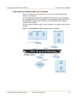
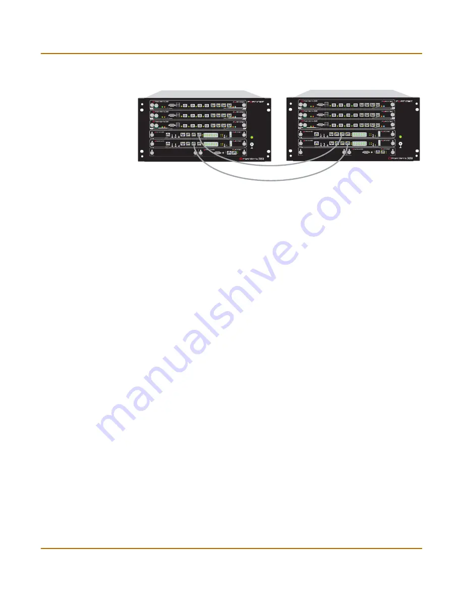
Figure 12: FortiGate-5050 inter-chassis cluster using redundant FortiSwitch-5003
modules
Next steps
Congratulations, you now have your FortiGate unit connected to your network. To fully
complete the installation:
•
Set the date and time
•
Register your FortiGate chassis and modules
•
Begin defining antivirus, intrusion and protection policies Refer to the
FortiGate
Administration Guide
for complete information on configuring, monitoring, and
maintaining the FortiGate unit.
Set the date and time
For effective scheduling and logging, the FortiGate system date and time must be
accurate. You can either manually set the system date and time or configure the
FortiGate unit to automatically keep its time correct by synchronizing with a Network
Time Protocol NTP) server.
To set the date and time
1
Go to
System > Config > Time
.
2
Select Refresh to display the current FortiGate system date and time.
3
Select your Time Zone from the list.
4
Optionally, select Automatically adjust clock for daylight saving changes check box.
5
Select Set Time and set the FortiGate system date and time.
6
Set the hour, minute, second, month, day, and year as required.
7
Select Apply.
To use NTP to set the FortiGate date and time
1
Go to
System > Config > Time
.
2
Select Synchronize with NTP Server to configure the FortiGate unit to use NTP to
automatically set the system time and date.
PWR ACC
STA IPM
CONSOLE
USB
1
2
3
4
5
6
7
8
PWR ACC
STA IPM
CONSOLE
USB
1
2
3
4
5
6
7
8
PWR ACC
STA IPM
CONSOLE
USB
1
2
3
4
5
6
7
8
1
2
2
3
4
5
ShMC
1
ShMC
POWER
ON
MANAGEMENT
SYSTEM
E1
ZRE
LED MODE
15
14
13
12
11
10
9
8
7
6
5
4
3
2
1
0
E2
OK
CLK
INT
EXT
FL
T
HOT SW
AP
RESET
FL
T
CONSOLE
E T H O
R S 2 3 2
Z R E 0
Z R E 1
Z R E 2
HOT SWAP
STATUS
ALARMS
MINOR
ALARM
RESET
CRITICAL
MAJOR
MANAGEMENT
SYSTEM
E1
ZRE
LED MODE
15
14
13
12
11
10
9
8
7
6
5
4
3
2
1
0
E2
OK
CLK
INT
EXT
FL
T
HOT SW
AP
RESET
FL
T
CONSOLE
E T H O
R S 2 3 2
Z R E 0
Z R E 1
Z R E 2
PWR ACC
STA IPM
CONSOLE
USB
1
2
3
4
5
6
7
8
PWR ACC
STA IPM
CONSOLE
USB
1
2
3
4
5
6
7
8
PWR ACC
STA IPM
CONSOLE
USB
1
2
3
4
5
6
7
8
1
2
2
3
4
5
ShMC
1
ShMC
POWER
ON
MANAGEMENT
SYSTEM
E1
ZRE
LED MODE
15
14
13
12
11
10
9
8
7
6
5
4
3
2
1
0
E2
OK
CLK
INT
EXT
FL
T
HOT SW
AP
RESET
FL
T
CONSOLE
E T H O
R S 2 3 2
Z R E 0
Z R E 1
Z R E 2
HOT SWAP
STATUS
ALARMS
MINOR
ALARM
RESET
CRITICAL
MAJOR
MANAGEMENT
SYSTEM
E1
ZRE
LED MODE
15
14
13
12
11
10
9
8
7
6
5
4
3
2
1
0
E2
OK
CLK
INT
EXT
FL
T
HOT SW
AP
RESET
FL
T
CONSOLE
E T H O
R S 2 3 2
Z R E 0
Z R E 1
Z R E 2

