25
AMP
DC VOLTAGE RANGE
-48V TO -58V
INPUT A
Negative
Postitive
RTN
-48dc
Optional modules
3
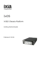
The FortiGate-5050 provides a scalable chassis that can include the following FortiGate modules.
FortiGate-5001 Antivirus Firewall
The FortiGate-5001 Antivirus Firewall is a high capacity module with FortiASIC
acceleration for real-time content security. The FortiGate-5050 can house up to
five FortiGate-5001 Antivirus Firewall modules.
FortiGate-5003 Switch Blade
The FortiGate-5003 Switch Blade provides redundant connections between
FortiGate-5001 blades on the backplane, and three external Gigabit interfaces.
Two FortiGate-5003 modules in a chassis enable high-availability failover
across chassis. The FortiGate-5050 chassis can house up to two
FortiGate-5003 Switch Blades.
FortiGate-5050SM Shelf Manager
The FortiGate-5050SM is responsible for powering a shelf up or down and
handling the adding and removal of modules including the switching of
interconnected resources. It also manages the power distribution and shelf
status of the FortiGate chassis. The FortiGate-5050 chassis can house up to
two redundant FortiGate-5050 Shelf Managers.
FortiGate-5053 Power Converte
r
The FortiGate-5053 Power Converter allows for AC power inputs, supports 2 +1
redundant hot-swappable modules, and up to three power supply modules. The
FortiGate-5053 Power Shelf can mount above or below the chassis.
Mounting the chassis
2
Mounting
•
Mount the FortiGate-5050 in a standard 19-inch rack. the
FortiGate-5050 requires 5U of vertical space.
•
If you install the FortiGate unit in a closed or multi-unit rack
assembly, the operating ambient temperature of the rack
environment may be greater than room ambient. Make sure the
operating ambient temperature does not exceed the
manufacturer's maximum rated ambient temperature.
•
Do not operate the FortiGate chassis as a free-standing appliance.
Air flow
•
Air flow is horizontal from right to left.
•
For rack installation, make sure that the amount of air flow required
for safe operation of the FortiGate unit is not compromised.
Mechanical loading
•
For rack installations, make sure the mechanical loading of the
FortiGate unit is evenly distributed to avoid a hazardous condition.
Power Supply
•
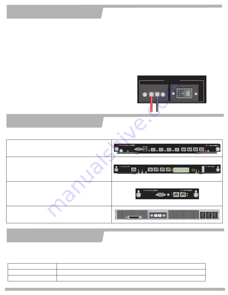
Two power connections on the back of the FortiGate-5050 chassis
supply -48VDC power to the power supplies.
•
If DC power is not available, you can install the FortiGate-5053
power converter to convert an AC power supply to DC.
To connect the DC power supply
1. Ensure the power switch is off on the chassis and power source.
2. Connect the negative (black) wire to the -48dc (Neg) screw
terminal.
3. Connect the positive (red) wire to the RTN (Pos) screw terminal.
4. Turn on the power source and power switch.
Technical support
4
Fortinet Technical Support Web site:
http://support.fortinet.com
Fortinet email support:
amer_support@fortinet.com
For customers in the United States, Canada, Mexico, Latin America and South America.
apac_support@fortinet.com
For customers in Japan, Korea, China, Hong Kong, Singapore, Malaysia, all other Asian countries, and Australia.
eu_support@fortinet.com
For customers in the United Kingdom, Scandinavia, Mainland Europe, Africa, and the Middle East.
PWR
STA IPM
CONSOLE
USB
1
2
3
4
5
6
7
8
MANAGEMENT
SYSTEM
E1
ZRE
LED MODE
15
14
13
12
11
10
9
8
7
6
5
4
3
2
1
0
E2
OK
CLK
INT
EXT
FL
T
HOT SW
AP
RESET
FL
T
CONSOLE
E T H O
R S 2 3 2
Z R E 0
Z R E 1
Z R E 2
HOT SWAP
STATUS
ALARMS
MINOR
ALARM
RESET
CRITICAL
MAJOR


