background image

Introduction 

Conventions

FortiManager-1000C™ Version 4.0 Rack and Hardware Install Guide
02-40000-112634-20091026

5

http://docs.fortinet.com/

 • 

Feedback

Typographical conventions

Fortinet documentation uses the following typographical conventions:

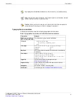
Tip: 

Highlights useful additional information, often tailored to your workplace activity.

Note: 

Also presents useful information, but usually focused on an alternative, optional 

method, such as a shortcut, to perform a step.

Caution: 

Warns you about commands or procedures that could have unexpected or 

undesirable results including loss of data or damage to equipment.

Table 1: Typographical conventions in Fortinet technical documentation

Convention

Example

Button, menu, text box, 
field, or check box label

From 

Minimum log level

, select 

Notification

.

CLI input

config system dns

set primary <address_ipv4>

end

CLI output

FGT-602803030703 # get system settings

comments            : (null)

opmode              : nat 

Emphasis

HTTP connections are 

not

 secure and can be intercepted by 

a third party.

File content

<HTML><HEAD><TITLE>Firewall 

Authentication</TITLE></HEAD>

<BODY><H4>You must authenticate to use this 

service.</H4>

Hyperlink

Visit the Fortinet Technical Support web site, 

https://support.fortinet.com

.

Keyboard entry

Type a name for the remote VPN peer or client, such as 

Central_Office_1

.

Navigation

Go to 

VPN

 > 

IPSEC

 > 

Auto Key (IKE)

.

Publication

For details, see the 

FortiGate Administration Guide

.

Summary of Contents for FortiManager-1000C

Page 1: ...FortiManager 1000C Version 4 0 Rack and Hardware Install Guide...

Page 2: ...FortiBIOS FortiBridge FortiClient FortiGate FortiGate Unified Threat Management System FortiGuard FortiGuard Antispam FortiGuard Antivirus FortiGuard Intrusion FortiGuard Web FortiLog FortiAnalyzer Fo...

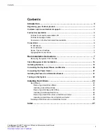
Page 3: ...pographical conventions 5 Rack Installation Instructions 7 Removing the system from the rack 14 Cable Management Arm Installation 14 Installing the Bezel 19 Connecting the Keyboard Mouse and Monitor 2...

Page 4: ...Contents FortiManager 1000C Version 4 0 Rack and Hardware Install Guide 2 02 40000 112634 20091026 http docs fortinet com Feedback...

Page 5: ...The Fortinet security system uses Fortinet s Dynamic Threat Prevention System DTPS technology which leverages breakthroughs in chip design networking security and content analysis The unique ASIC acce...

Page 6: ...it the Fortinet Technical Documentation web site http docs fortinet com Fortinet Knowledge Center The Fortinet Knowledge Center provides additional Fortinet technical documentation such as troubleshoo...

Page 7: ...equipment Table 1 Typographical conventions in Fortinet technical documentation Convention Example Button menu text box field or check box label From Minimum log level select Notification CLI input c...

Page 8: ...Conventions Introduction FortiManager 1000C Version 4 0 Rack and Hardware Install Guide 6 02 40000 112634 20091026 http docs fortinet com Feedback...

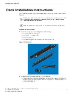
Page 9: ...straps 3 Two cable management arm CMA attachment brackets 4 Figure 1 Rail kit contents 2 To install the rails in square hole racks do the following Position the left and right rail end pieces of the r...

Page 10: ...il until it fully seats on the vertical rack flange and the second tooth on the latch locks in place Repeat these steps to position and seat the front end piece on the vertical flange 7 To remove the...

Page 11: ...he back end of the rail until it fully seats on the vertical rack flange and the first tooth on the latch locks in place Repeat these steps to position and seat the front end piece on the vertical fla...

Page 12: ...one locks into place To remove the chassis rail members lift the lock spring until it clears the head of the pin 14 Slide the chassis rail member toward the front of the system until the pins slip thr...

Page 13: ...ck Align and insert the ends of the chassis rail members into the ends of the rails 16 Push the system inward until the chassis rail members lock into place Push or pull the blue tab located near the...

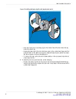
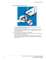
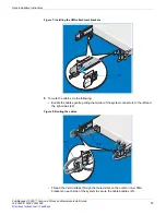
Page 14: ...ystem for shipment in the rack or for other unstable environments locate the hard mount screw under each latch and tighten each screw with a 2 Phillips screwdriver 20 7 To install the CMA attachment b...

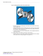
Page 15: ...Installing the CMA attachment brackets 8 To route the cables do the following Bundle the cables gently pulling them clear of the system connectors to the left and the right sides 22 Figure 8 Routing...

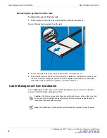
Page 16: ...the front of the system to release the chassis rail members from the rails Continue pulling the system until the chassis rail members are completely clear of the rails and place the system on a level...

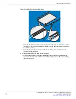
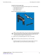
Page 17: ...s 2 To install or remove the Cable Management Arm Tray do the following Align and engage each side of the tray with the receiver brackets on the inner edges of the rails and push forward until the tra...

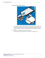
Page 18: ...receiver brackets 5 3 To install and remove the CMA do the following At the back of the system fit the latch on the front end of the CMA on the innermost bracket of the slide assembly until the latch...

Page 19: ...nd removing the Cable Management Arm Fit the other latch on the end of the outermost bracket until the latch engages 7 To remove the CMA disengage both latches by pressing the CMA release buttons at t...

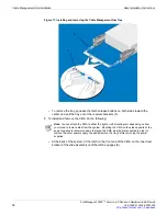
Page 20: ...ce it is unseated from the tray swing the CMA away from the system 10 5 To cable the system using the CMA do the following Using the tie wraps provided bundle the cables together as they enter and exi...

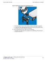
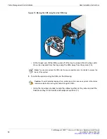
Page 21: ...into place on the tray 15 Install the status indicator cable at the back of the system and secure the cable by routing it through the CMA Attach the other end of this cable to the corner of the outer...

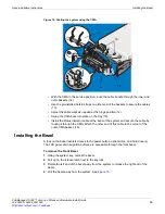
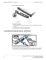
Page 22: ...on the right side of the system front panel 2 Rotate the left side of the bezel toward the system 3 Press the bezel to the system to engage the latch Connecting the Keyboard Mouse and Monitor Figure 1...

Page 23: ...ed connect the monitor s power cable to the monitor Installing the Power Cord Retention Bracket Figure 18 Installing the power cord retention bracket Attach the power cord retention bracket on the rig...

Page 24: ...Manager 1000C Version 4 0 Rack and Hardware Install Guide 22 02 40000 112634 20091026 http docs fortinet com Feedback Turning on the System Figure 19 Turning on the system Press the power button on th...

Page 25: ...el See Installing the Bezel on page 19 2 Grasp the front of the hard drive blank press the release lever on the right side and slide the blank out until it is free of the drive bay See Figure 1 Figure...

Page 26: ...4 Slide the hard drive out of the drive bay 5 Insert a drive blank in the vacated drive bay See Installing a Hard Drive Blank 6 If applicable install the bezel See Installing the Bezel on page 19 Inst...

Page 27: ...drive carrier When aligned correctly the back of the hard drive will be flush with the back of the hard drive carrier 3 Attach the four screws to secure the hard drive to the hard drive carrier Figure...

Page 28: ...1000C Version 4 0 Rack and Hardware Install Guide 26 02 40000 112634 20091026 http docs fortinet com Feedback Figure 4 Installing a Hard Drive Into a Drive Carrier 1 drive carrier 2 screws 4 3 hard d...

Page 29: ...25 F Fortinet customer service 3 Fortinet documentation 4 commenting on 4 Fortinet Knowledge Center 4 H hard drive drive carrier 25 installing 24 removing 23 hot swap hard drives 23 I installing bezel...

Page 30: ...Index FortiManager 1000C Version 4 0 Rack and Hardware Install Guide 28 02 40000 112634 20091026 http docs fortinet com Feedback...

Page 31: ...www fortinet com...

Page 32: ...www fortinet com...

Reviews: