background image

10

11

Installation

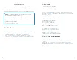
The FortiSandbox unit can be placed on a 

flat surface

 using the provided rubber feet, or 

mounted in any standard 

19 inch rack

 unit with the provided mounting rails. 

Please also read 

"Cautions and Warnings" on page <?>

 prior to installing your device.

Caution:

 The rack must be 

stabilized

 before sliding the unit out for servicing. 

Failure to stabilize may cause the rack to 

tip over

.

Electrostatic discharge

 (ESD) can damage your Fortinet equipment. 

To avoid personal 

injury

 or 

damage

 to the unit, it is recommended that 

two or more


people install the unit into the rack.

Do not place 

heavy objects

 on the unit.

Rack Precautions

•  Ensure the 

leveling jacks

 on the bottom of the rack are 

fully extended

 to the floor with 

the full weight of the rack resting on the jacks.

•  For single rack installation, 

stabilizers

 should be attached to the rack.

•  For multiple rack installations, the racks should be 

coupled together

.

•  Ensure the rack is 

stable

 before extending a component from the rack.

•  Only extend 

one component

 at a time; extending 

two or more

 simultaneously may 

cause the rack to become 

unstable

.

Rack Rail Parts

The 

rail assembly

 consists of 

two parts

:

• 

Outer rail

: connects to the rack

• 

Inner rail

: connects to the device

The 

inner rail

 has a 

locking tab

 that locks the device into place when it is installed and 

pushed into the rack. This 

prevents

 the device from 

sliding

 fully out of the rack when the 

device is being worked on.

There are 

four steps

 to install the device into the rack:

1. 

Disassemble

 the rail assembly

2. 

Attach the 

inner rails

 to the device

3. 

Install the 

outer rails

 on a rack

4. 

Install the device into 

the rack

Disassemble the rail assembly

1. 

Identify the left and right 

rail assemblies

.

2. 

Pull out

 the inner rail until it is fully extended.

3. 

Push the 

white locking tab

 to release the inner rail.

4. 

Remove the 

inner rail

 from the 

outer rail

.

5. 

Repeat steps 2 - 4 for the remaining rail assembly.

Attach the inner rails to the device

1. 

Ensure that the 

right and left rails

 are correctly identified.

2. 

Place the 

inner rail

 against the side of the device and ensure that the screw 

holes

 are 

aligned.

3. 

Secure the rail to the device using 

five

 of the provided 

M4 Waffle Head screws

.

4. 

Attach the 

sliding rail handle

 to the device using 

three

 of the provided 

M4 Flat Head 

screws

.

5. 

Repeat steps 2 - 3 for the remaining inner rail.

Summary of Contents for FortiSandbox 1000F

Page 1: ...FortiSandbox 1000F FSA 1000F FSA 1000F DC QuickStart Guide ...

Page 2: ...nt Fortinet enters a binding written contract signed by Fortinet s General Counsel with a purchaser that expressly warrants that the identified product will perform according to certain expressly identified performance metrics and in such event only the specific performance metrics expressly identified in such binding written contract shall be binding on Fortinet For absolute clarity any such warr...

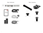
Page 3: ...x Includes Power Cable Ethernet Cable 5x Rubber Feet 2x Sliding Rails 2x Sliding Rail Handles 6x M4 Flat Head Screws 2x Rack Mount Screws 10x M4 Waffle Head Screws Console Cable FortiSandbox 1000F 4 5 QuickStart Guide ...

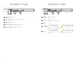
Page 4: ... A B not in use FSA 1000F FSA 1000F DC 4 2 3 5 1 Green The device is on Off The device is off Not in use Red Device failure Off Device is running normally POWER STATUS HDD ETHERNET SFP Ports Link Activity Left LED Flashing Amber Data activity Off No link established Ports Speed Right LED Amber Connected at 1Gbps Green Connected at 100Mbps Off Connected at 10Mbps or off Ports Link Activity Left LED...

Page 5: ...Power 48V DC 9A DC Input GND power supply ground E S D 4 5 3 1 2 3 4 5 3 3 Green PSU operating normally Flashing Green PSU on standby Flashing Red No power to the PSU Red PSU failure Off PSU is off Blue DC PSU operating normally Flashing Blue DC standby on Flashing Red No power to the PSU Red PSU failure Flashing Red Blue PSU warning Off PSU is off AC Power Supply LED DC Power Supply LED RTN 36V 7...

Page 6: ...se the rack to become unstable Rack Rail Parts The rail assembly consists of two parts Outer rail connects to the rack Inner rail connects to the device The inner rail has a locking tab that locks the device into place when it is installed and pushed into the rack This prevents the device from sliding fully out of the rack when the device is being worked on There are four steps to install the devi...

Page 7: ...es while pushing the device all the way into the rack 5 For additional security secure the handles to the front of the rack with the two provided rack mount screws To remove the device from the rack pull it out as far as it will go then push the locking tabs on both sides and slide the device out After the device is installed in the rack plug the provided power cable into the rear of the unit and ...

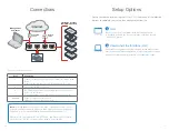
Page 8: ... the device using the GUI Connect to the Internet to access FortiGuard and FortiCare 2 High Availability HA connection 3 The VM outgoing port allows possibly malicious connections to connect to the Internet This port should be connected through an isolated network 4 and up Connect FortiGate or other devices Optionally can be used as sniffer ports Connections Note The FortiSandbox unit requires som...

Page 9: ...iSandbox Management Computer Port 1 Browse to 192 168 1 99 Username admin No Password GUI A CLI B 1 Connect the Console Port with a console cable to the Management Computer 2 Start a terminal program on the Management Computer and select an available COM Port using the following default settings Baud rate 9600 Data bits 8 Parity None Stop bits 1 Flow control None 3 Log in using username admin and ...

Page 10: ...ip Set the default gateway reboot Reboot the FortiSandbox All sessions will be terminated shutdown Shut down the FortiSandbox status Show various system information For example to configure the IP address and gateway of the FortiSandbox device use the following commands set port1 ip 192 168 0 10 24 set default gw 192 168 0 1 Useful CLI Commands A limited CLI is available for basic device configura...

Page 11: ...èce Par conséquent il est important d installer le matériel dans un environnement respectant la température ambiante maximale Tma stipulée par le fabricant Reduced Air Flow Installation of the equipment in a rack should be such that the amount of air flow required for safe operation of the equipment is not compromised Ventilation réduite Installation de l équipement dans un rack doit être telle qu...

Page 12: ......

Page 13: ...docs fortinet com Training Services Course descriptions availability schedules and location of training programs in your area https www fortinet com support and training training html Technical Discussion Forums Communicate with other customers and Fortinet partners about Fortinet products services and configuration issues https support fortinet com forum FortiGuard Threat Research and Response Up...

Reviews: