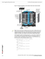
FortiGate-5140 fabric backplane communication
Fabric 10-gigabit switching within a chassis
FortiSwitch-5003A and 5003 Fabric and Base Backplane Communications Guide
01-30000-85717-20081205
31
Fabric 10-gigabit switching within a chassis
All of the FortiSwitch-5003A fabric front panel interfaces are 10-gigabit interfaces
and the FortiSwitch-5003A board supports 10-gigabit communication across the
fabric backplane channels. The FortiGate-5001A board also supports 10-gigabit
communication on the fabric backplane with the addition of a FortiGate-RTM-XB2
module. You require one FortiGate-RTM-XB2 module for each FortiGate-5001A
board. The FortiGate-RTM-XB2 module must be installed in the chassis rear
transition module (RTM) slot that corresponds to the front panel slot containing
the FortiGate-5001A board. For example, if you install a FortiGate-5001A board in
slot 3 you must also install a FortiGateRTM-XB2 module in RTM slot 3. The RTM
slots are at the back of the FortiGate-5140 chassis.
One FortiGate-RTM-XB2 module provides 10-gigabit connections to both fabric
channels. The FortiGate-RTM-XB2 also provides NP2 packet acceleration for
both fabric channels. To effectively use NP2 acceleration, packets must be
received by the FortiGate-5001A board on one fabric channel and must exit from
the FortiGate-5001A board on the same fabric channel or on the other fabric
channel. See the
FortiGate-RTM-XB2 System Guide
for more information about
the FortiGate-RTM-XB2.
Figure 13
shows a FortiGate-5140 chassis containing two FortiSwitch-5003A
boards and six FortiGate-5001A boards. Using these components this chassis
supplies 10-gigabit connectivity between the external and internal networks. The
external network is connected to the F1 10-gigabit front panel interface of the
FortiSwitch-5003A board in slot 1, which connects the external network to fabric
channel 1. The internal network is connected to the F7 10-gigabit front panel
interface of the FortiSwitch-5003A board in slot 2, which connects the internal
network to fabric channel 2.
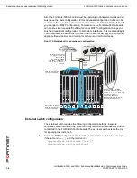
10-gigabit traffic from the external network enters the F1 10-gigabit
FortiSwitch-5003A front panel interface, passes through the FortiSwitch-5003A
board and through the FortiGate-RTM-XB2 modules to the fabric1 interfaces of
the FortiGate-5001A boards. Traffic accepted at the fabric1 interfaces is
processed by each FortiGate-5001A board. Traffic destined for the internal
network exits the fabric2 interfaces of the FortiGate-5001A boards, passes
through the FortiGate-RTM-XB2 modules and through the FortiSwitch-5003A
board and exits the F7 10-gigabit FortiSwitch-5003A front panel interface and is
received by the internal network.
The configuration shown in
Figure 13
requires no configuration changes to the
FortiSwitch-5003A boards except to disable communication between the
FortiSwitch-5003A boards (if required, see
“Fabric channel connections between
FortiSwitch-5003A boards” on page 27
).
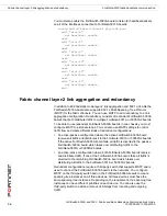
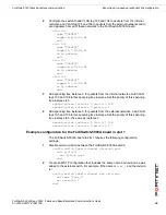
On the FortiGate-5001A boards, to allow traffic to pass between the internal and
external networks, the FortiGate-5001A boards would operate in NAT/Route
mode and you must configure firewall policies and routing for the fabric1 and
fabric2 interfaces. No configuration changes are required to use the
FortiGate-RTM-XB2 module. NP2 acceleration is automatically applied to traffic
passing between the internal and external networks by the FortiGate-RTM-XB2
module.
Note:
A single FortiSwitch-5003A can provide simultaneous 10 Gbps connections to
FortiGate-5001A boards with FortiGate-RTM-XB2 modules, 1 Gbps connections to
FortiGate-5001A boards, and 1 Gbps connections to FortiGate-5005FA2 boards.


