background image

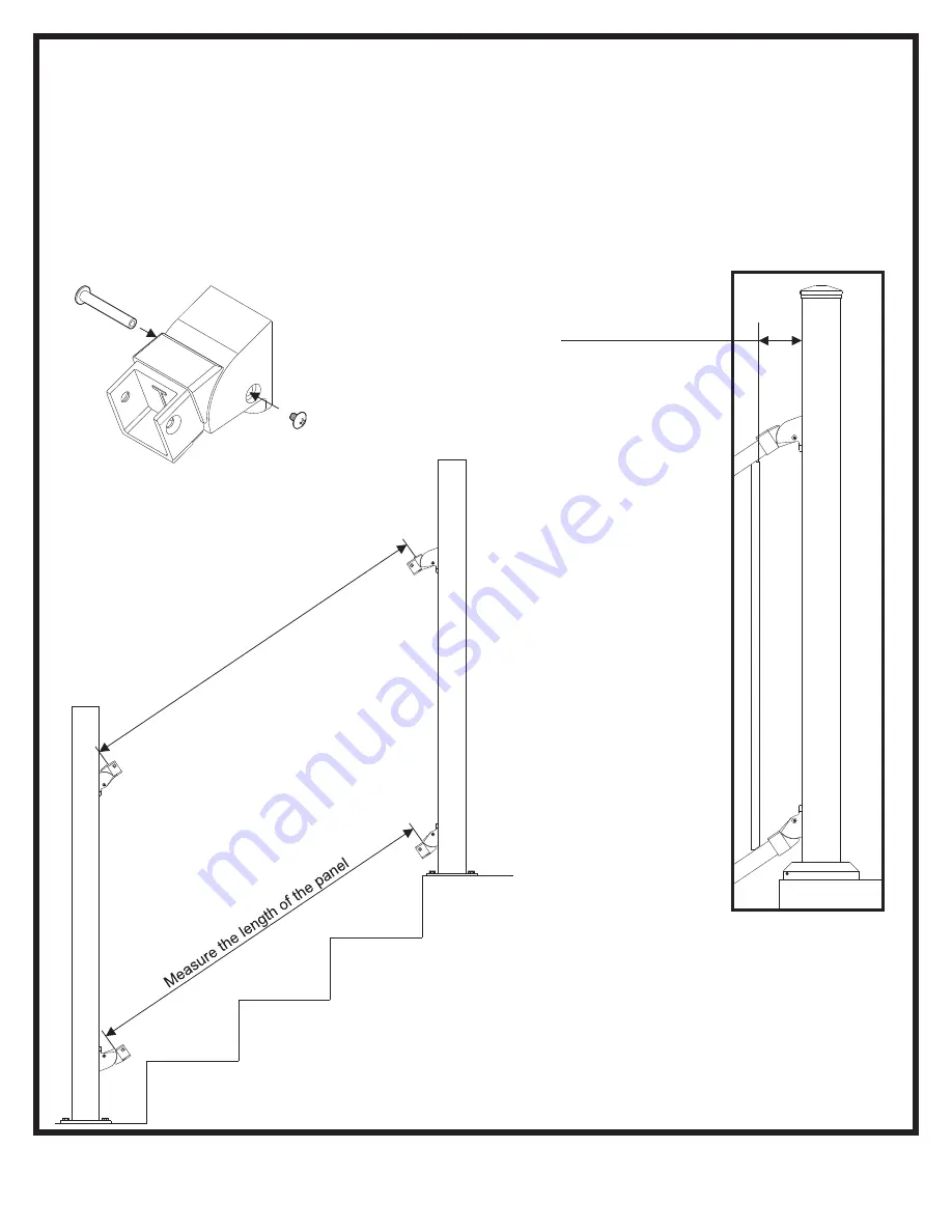
OTP & Proud Post: Measuring the Length of the Panel

• Reassemble the stair brackets.
• Measure the distance from the inside edge of the bottom two brackets.
• Check that the distance is the same between the top brackets. If the measurement is different, use shims to level the posts.
• Transfer this measurement to the panel. See the proper cutting instructions in the next step.

Post to baluster space 

must be less than 4”

Confirm measurement

9/15

Summary of Contents for Al13 HOME

Page 1: ...ation Note When cutting Fortress railing it is very important to complete the following at cut points Remove all metal shavings from the cut area File any sharp edges left by cutting Thoroughly wipe and remove any filings grime or dirt from the railing Apply two coats of Fortress zinc based touch up paint to the cut area If touch up is at rail ends allow paint to dry before connecting bracket to p...

Page 2: ...or a line post if you are installing an Over the Post System A 2 post can be used on end post and corner post locations if the panel is installed without an Accent Top Rail Over The Post With Accent Top Rail ATR Panel With or Without Accent Top Rail ATR Panel Only Without Accent Top Rail ATR 3 x 51 Post 3 x 51 Post 2 x 51 Post 2 x 51 Post or 3 x 51 Post 2 x 51 Post or 3 x 51 post 3 x 51 Post 3 x 5...

Page 3: ...se Cover Post Base Cover Flat Accent Top Rail ATR Round Accent Top Rail ATR 2 Post Round ATR Stair Line Splice Flat ATR Stair Line Splice 13 Al HOME Panels Stair Angle 20 to 40 13 Al HOME Simplified Stair Brackets 13 Al HOME Simplified Stair Brackets 13 Al HOME Simplified Stair Brackets Post Base Cover I Support I Support 3 15 ...

Page 4: ...20 to 40 3 Post 3 Post Flat Accent Top Rail ATR Round Accent Top Rail ATR Post Base Cover Post Base Cover 13 Al HOME Simplifed Stair Brackets 13 Al HOME Simplified Stair Brackets 13 Al HOME Simplified Stair Brackets 13 Al HOME Simplified Stair Brackets Post Cap Post Cap I Support 4 15 ...

Page 5: ...ntify the 4 brackets labeled LT ST LB and SB by the letters stamped on each part Locate the 2 bottom rail brackets LB and SB Place each bracket on top of the 2 x 4 and flat against the post Find the center of the posts and mark the top screw location After confirming the hole spacing posts can be attached to the deck surface Do not exceed the max height for the top screw location See the table bel...

Page 6: ...e template Align the edge of the template to the side of the post Note that one side of the template is for a 2 post and other is for a 3 post Mark all the hole locations for the brackets using a center punch There will be 4 holes total on each post face Alternatively the hole spacing is 7 8 between the bracket holes and 28 1 4 for a 32 5 panel and 35 3 4 for 40 panels between the holes on the top...

Page 7: ... The outside bracket hole is slotted to allow for movement to make the bracket vertical The second hole can be drilled out or you can use the drill tip on the screw to start the second screw Check the vertical position of the brackets before tightening down TopPost Bottom Post Top Bracket Bottom Bracket 1 Attach center screw 2 Attach outside screw 3 Rotate bracket to be vertical 4 Tighten both scr...

Page 8: ...op brackets This will be your cut line This line can be up to 3 8 above the brackets Use a reciprocating saw or portable band saw to cut the post along this line After cutting the post file the rough edges and paint the exposed surface using Fortress touch up paint pen Cut line 1 2 3 4 3 8 Max 3 8 Max Paint pen Before After 8 15 ...

Page 9: ...de edge of the bottom two brackets Check that the distance is the same between the top brackets If the measurement is different use shims to level the posts Transfer this measurement to the panel See the proper cutting instructions in the next step Post to baluster space must be less than 4 Confirm measurement 9 15 ...

Page 10: ...ll OTP and Proud Post Cut Down Panel to Correct Length To insure both ends of the panel look the same divide the bracket to bracket measurement by 2 to find half of the panel length From the center of the panel measure out half of the length each direction Mark these locations with a paint pen or other tool on the top and bottom rails Example 78 2 39 Measure out 39 from the center point in both di...

Page 11: ...el down into the brackets Push the bracket up so that the bottom is parallel with the rail Attach the panel using the T 25 screw that came with the brackets Attach the screws on the same side of the panel Only 1 screw in each corner is required Remove any metal shavings after attaching the panel 11 15 ...

Page 12: ...cover OTP and Proud Post I Support Installation The I Support should be located near the center of the panel directly under a baluster The I Support can rotate to any angle 0 to 40 The height of the I Support can change from 3 3 up to 5 7 Install the I Support by snapping the rail insert up into the bottom rail Position the I Support directly under a baluster Unscrew the base until it reaches the ...

Page 13: ...more then 14 spacing between them The end spacers should be placed as close to the end brackets as possible Attach spacers using provided self drilling screws with a 5 16 nut driver Two screws per spacer Do not remove backing of double sided tape until you are ready to permanently attach the ATR 14 Max Double sided tape Spacer mounted next to stair bracket 13 15 ...

Page 14: ...en test fitting the ATR place it on top of the spacers Do not press the ATR down over the spacers Removing the ATR from the spacers can damage the ATR and spacers If you are installing a OTP Line Post see the next page before permanently installing the ATR Make sure the inside of the ATR is clean before remove the backing of all of the double sided tape on the ATR spacers Using force the ATR snaps...

Page 15: ... the ATR as mentioned in the previous step It is recommended that the ATR and post splice are test fitted together above the rail before installing Attach the ATRs to the panels first Snap the splice over the ATRs Once in position use the supplied self drilling screws 2 to attached the splice to the post Post caps to be pressed down to secure Use a broom or air compressor to remove debris from rai...

Reviews: