Mechanical Function Test Instructions
Test 1
1.
Rotate and remove the Personnel key from the PBL device.
• It must not be possible to rotate and remove the PBL Blocker Plate from its Engaged position with the Personnel
Key removed.
• The safety output from the associated Light Curtain or Photoelectric sensing device must indicate that the sensing
beam or zone is blocked or interrupted.
• It must not be possible for a machine restart signal to be generated until the Personnel Key has been reinserted
and rotated.
5
Operating Instructions: Photoelectric Blocking - PBL
Tools and Fixings Required
• Minimum 2 x M8 screws or 2 x M5 screws for securing PBL device.
• Screws must be suitable length for a minimum of 10mm thread engagement.
• Screws must be security type to prevent unauthorised removal or tampering.
• Required torque setting; 40 Nm.
• 2 x M8 or 2 x M5 Nut / T-Nut / Threaded Hole for securing PBL device.
• Driver suitable for securing M8 or M5 screws.
•
Adhesive Threadlocker to secure mounting fixings from loosening due to vibration.
Mounting
1.
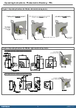
Locate the PBL device so that it can correctly interrupt or block the signal of the associated Light Curtain or Photoelectric
sensing device to which it is mounted with its Blocker plate in its engaged position. See Fig.2 for mounting dimensions.
2.
Secure the PBL device using minimum 2 x M5 screws through the available mounting holes at the top and bottom of its
mounting plate.
3.
Perform Mechanical Function tests before completing installation and commission. See Mechanical Function test section
for more details.
Mount the complete device only in the correctly assembled condition.
•
All mounting surfaces should be flat, stable and suitable of providing a minimum of 10mm thread engagement or sufficient
support to either an M8 Nut/T-Nut or M5 Nut/T-Nut.
• The PBL device must be located so that all scheduled inspection and maintenance procedures are all easily possible.
• The complete machine guarding installation must conform to all relevant design, construction and installation standards
and guidelines.
• Any gap around the perimeter of the machine and guarding when under operation (Safety Outputs High) must not exceed
the limits specified in ISO 13857 & ISO 14120.
•
All fixing screws used to mount the complete Device must be permanently prevented from removal. If mounting fixings are
visible, they must be secured against removal by personnel using standard tools, manipulation and un-authorised or un-
identifiable removal. If mounting fixings are not visible or hidden, they must be secured against removal or loosening due to
vibration. In both cases, a middle strength adhesive threadlocker is required.
Service and Inspection
Regular inspection of the following is necessary to ensure trouble-free, lasting operation:
• Correct operating function
• Secure mounting of components
• Debris and wear
• WD40 lubricant or equivalent, should be applied to each mechanical element every 10,000 operations, or sooner, to ensure
smooth product operation and function. There are no user serviceable parts in this product. If damage or wear is found with
an assembly, please contact your local Fortress Channel Partner for a replacement. The complete device must be replaced
after 1 million operations.


