Operation Maintenance Manual
Safety Spinning Wrench
PN 9GV73109 - Revision: 02 2018-05
46
C
O
M
M
IS
SION
IN
G
/
O
PE
R
A
TION
4.2.1
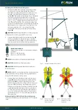
Positioning and clamping the
SSW-40
1. Locate the lift handle
q
. Raise the SSW-40 to the
proper position, about 12” above the tool joint.
2. Position the SSW-40 on the pipe upset or tool joint.
3. Proper clearance is ½” between the pipe and the front
rollers.
4. Turn the adjustment screw to engage the socket.
Proper clearance is ½” between the pipe and the front
rollers.
5. Turn the adjustment handle either clockwise or
counter clockwise to close the distance between the
bodies or to open it up.
6. Push the clamp control
w
to clamp down on the pipe.
7. Pull the clamp control
w
lever to unclamp the pipe
and then swing the SSW-40 away from the pipe.
4.2.2
Motor Direction
1. Position the lockout
q
to spin in the desired direction,
spin in or spin out.
2. The lockout will prevent spinning in the undesired
direction.
3. Push the throttle control lever
w
to spin in or
pull to spin out.
Handling the adjustment screw
1. Pull out the adjustment handle out of the adjustment
screw
q
.
2. Fold over the adjustment handle at the joint.
3. Set the necessary diameter while turning the handle
clockwise or anticlockwise
w
.
4. Follow the adjustment operation in reverse order, after
setting the necessary diameter.
CAUTION
Only operate the SSW-40 when adjustment
handle is hidden in the adjustment screw.
Fig. 31: Positioning valve of the SSW-40
Fig. 32: Spinning direction valve
Fig. 33: SSW-40 Adjustment screw
q
w
w
q
q
w


