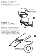
14
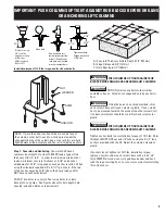
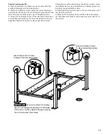
M12 x 20 BOLT
Ø12 LOCKWASHER
Ø12 FLAT WASHER
FRONT CHOCK
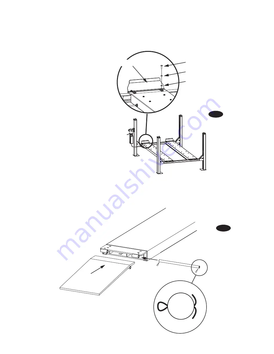
SPREAD COTTER PINS
AFTER INSTALLATION
Fig. 19
Fig. 20
Step: 14: Front Chock and Approach Ramp Installation:
A.) Attach front chock as shown, Fig. 19.
B.) Attach approach ramp with bar and cotter pins as shown, Fig.
20. Be sure to spread cotter pins after installation.
Step 15: Testing Your Lift:
A.) Push button on power unit to raise your lift.
B.) Pulling up on lock lever will release locking latches.
C.) Push down on the lowering valve to lower lift.
Note:
Without pulling up on the lock lever the lift will only lower
onto the locking latches. Any time you lower the lift you will have
to raise your lift off of the locking latches, (approximately 1 inch),
and pull up on the lock lever to allow the locking latches to clear
the slots in the latch bars. Releasing the lock lever will re-engage
the locks. The lift will stop in the next locking position unless you
are below the lowest slots in the latch bars. After you clear the
lowest slots in the latch bars the lock lever may be released and
the lift will completely lower the lift to the ground.


