General
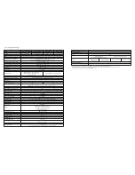
Capacity
Topology
Input
Nominal voltage
Voltage range (low line transfer)
Voltage range (low line comeback)
Voltage range (high line transfer)
Voltage range (High Line comeback)
Frequency
Power factor
Total harmonic distortion (THDi)
AC plug style
Output
Nominal voltage
AC voltage regulation (battery mode)
Frequency (synchronized range)
Frequency (battery mode)
Power factor
Efficiency (AC mode)
Efficiency (battery mode)
Overload
Transfer time (line to battery)
Transfer time (inverter to bypass)
Crest ratio
Harmonic distortion
Waveform
Type of outlet
Battery pack (included)
Battery type and quantity
Recharge time
Charging current
Charging voltage
Communications
LCD display
Visual indicators
Audible
Communication ports
Power management software
Special features
"Cold start” option
Auto charge
Environment
Operating temperature
Storage temperature
Relative humidity
Operating altitude
Audible noise
Physical appearance
Housing
Color
Dimensions
Weight
Additional information
Warranty
6000VA/6000W
10000VA/10000W 6000VA/6000W
10000VA/10000W
Double conversion
110-300VAC
176VAC / 140VAC / 110VAC ± 3%
(based on load percentage 100%-80% / 80%-60% / 60%-0%)
Low line transfer v 10V
300VAC ± 3%
High line transfer voltage - 10V
46-54Hz at 50Hz system / 56-64Hz at 60Hz system
≥0.99 at 100% load
<4% at 100% load / <6% at 50% load
Hard wired
± 2%
± 1%
46-54Hz at 50Hz system / 56-64Hz at 60Hz system
50Hz ± 0.1Hz or 60Hz ± 0.1Hz
1
> 91%
> 94%
> 90%
> 92%
AC mode: 100%-110%: 10min / 110%-130%: 1min / >130%: 1sec
Battery mode: 100%-110%: 30sec / 110%-130%: 10sec / >130%: 1sec
0ms
0ms
3:1 (max)
≤2% THD (linear load) / ≤6% THD (non-linear load)
≤1% THD (linear load) / ≤4% THD (non-linear load)
Pure sine wave
Terminal block
12V / 9Ah (20)
7 hours to 90% capacity
1A ± 10% (max) standard model / 4A ± 10% (max) long-run model
273VDC ± 1%
Graphical LCD with blue backlight
Status LEDs
Battery mode: Sounds every 4 seconds
Low battery: Sounds every second
Overload: Sounds every 0.5 second
Fault: Continuous sound
SNMP, RS-232, USB
ForzaTracker
Included
Included
32°F-104°F
UPS: -5°F-140°F
Battery: 32°F-95°F
0 -90% non-condensing
<1000m
Every 100m above 1000m decreases output power 1% up to 4000m
<55dB at 1 meter
ABS and metal
Black
2 years
MPN
FDC-106KMR
FDC-110KMR
FDC-206KMR
FDC-210KMR
Standard operation: 208/220/230/240VAC
With step-down isolation transformer:
104/110/115/120VAC
Standard operation: 208/220/230/240VAC
With step-down isolation transformer:
104/110/115/120VAC
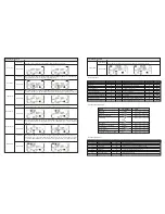
Even when utility power is normal, there is
no indication on the front panel and the
alarm has gone off.
The icon and the warning code blink
on the LCD display, and the alarm starts
beeping once every second.
The and icons become illuminated
on the LCD display, and alarm starts
beeping once every second.
The and icons blink on the LCD
display, and the alarm starts beeping twice
every second.
Fault code 43 becomes illuminated along
with the icon on the LCD display, and
the alarm starts beeping continuously.
Fault code 14 becomes illuminated along
with the icon on the LCD display, and
the alarm starts beeping continuously.
Fault code 01, 02, 03, 04, 11, 12, 13, 14,1A,
21, 24, 35, 36, 41, 42 or 43 become
illuminated on the LCD display, and alarm
starts beeping continuously.
Battery backup time is shorter than its
nominal value.
The AC input cable is not properly
connected.
EPO function is enabled.
The external or internal battery connection
is incorrect.
UPS is overloaded.
UPS is overloaded. Devices connected to
UPS are fed directly with utility power
through Bypass
After repetitive overloads, the UPS is
locked in Bypass mode.
Connected devices are fed directly from
utility power.
The UPS malfunctions due extended
system overload.
The UPS will shut down automatically.
The UPS shuts down automatically
because the output is short circuited.
A UPS internal fault has occurred. There
are two
possible causes:
1. Power is continued to be supplied to
the load, but is done directly from the AC
grid via a bypass.
2. Power is no longer supplied to the load.
Batteries are not fully charged
Defective batteries
Check to make sure the power cord is
firmly connected to the AC mains outlet.
Set the circuit in its closed position to
disable the EPO function.
Check if all batteries are properly
connected.
Remove excess loads from the UPS
output.
Remove excess loads from the UPS
output.
Remove excess loads from the UPS
output first. Then shut down the UPS and
restart the unit once again.
Remove excess loads from the UPS
output and restart the unit once again.
Check the output wiring and if the
connected devices are short-circuited.
Contact the dealer or service center.
Charge the batteries for at least 7 hours
and then check their capacity.
If the problem persists, consult your
dealer.
Contact your dealer for a replacement.
Symptom
Possible cause
Solution
-25°C - 40°C
40°C - 45°C
Every 3 months
Every 2 months
1-2 hours
1-2 hours
Storage temperature
Recharge frequency
Runtime
5. Storage and maintenance
5-1. Storage
4. Troubleshooting guide
If the UPS system does not operate correctly, use the table below to troubleshoot the problem.
Charge the UPS for at least 7 hours before storing the unit. Cover the UPS, and place it upright in a cool, dry location. During
storage, recharge the battery in accordance with the following table:
5-2. Maintenance
The UPS system operates with hazardous voltages. Repairs may be carried out only by qualified maintenance personnel.
Even after the unit is disconnected from the mains, components inside the UPS system are still connected to the battery packs
which are potentially dangerous.
Before carrying out any kind of service and/or maintenance, disconnect the batteries and verify that no current is present and no
hazardous voltage exists in the terminals of high capability capacitor such as BUS-capacitors.
Servicing of batteries should be performed or supervised by personnel with knowledge of batteries and the required precau-
tions. Keep unauthorized personnel away from batteries.
Verify that no voltage between the battery terminals and the ground is present before maintenance or repair. In this product, the
battery circuit is not isolated from the input voltage. Hazardous voltages may occur between the battery terminals and the
ground.
A battery can present a risk of electric shock and high short circuit current. The following precaution should be observed when
working on batteries:
- Remove watches, rings or other metal objects.
- Use tools with insulated handles.
Replace batteries with the same type and number of units.
Do not attempt to dispose of batteries by burning them. This could cause battery explosion. The batteries must be properly
deposed according to local regulations.
Do not open or destroy batteries. Released electrolyte is highly poisonous and harmful to the skin and eyes.
Replace the fuse only with the same type and amperage in order to avoid fire hazards.
Do not disassemble the UPS system.
Summary of Contents for FDC-106KMR-ISO
Page 17: ......


