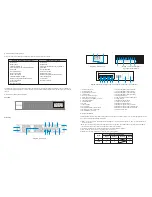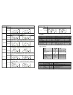
Description
UPS status
Bypass mode
Battery mode
Fault mode
Warning
Overload
Other alert
Fault
All
Buzzer status
Beeps once every 2 minutes
Beeps once every 4 seconds
Beeps continuously
Beeps twice every second
Beeps once every second
Beeps continuously
Yes
Yes
Yes
Muted
2) Press and hold the
ON
button for 0.5 second to power on the UPS. The buzzer will beep once.
3) After a few seconds, the UPS will enter into the AC mode. In case of abnormal utility power, the UPS will transfer to battery
mode operation to provide uninterrupted power to the outlets.
Note:
In battery mode, the UPS will shut down automatically when the remaining charge is low. Once the utility power is
restored, the UPS will restart automatically in AC mode.
2. Turn on the UPS without utility power (Battery mode)
1) Make sure that the battery pack breaker is in its
ON
position.
2) Press and hold the
ON
button for 0.5 second to power on the UPS. The buzzer will beep once.
3) After a few seconds, the UPS will be turned on and begin operating on “off-grid” or Battery mode.
3. Connecting devices to the UPS
After the UPS is turned on, you can connect devices to the unit.
1) Turn on the UPS first and then start powering one load at a time only after all of them have been plugged into the unit. The total
load level will be displayed on the LCD panel.
2) Should you need to connect inductive loads, such as a monitor or a laser printer to the UPS, the start-up power should be used
for calculating the capacity of the UPS, as energy consumption increases during initial power on.
3) If the UPS is overloaded, the buzzer will beep twice every second.
4) In the event of an overload, all unnecessary loads must be removed one by one, to lower the total loads connected to the UPS to
less than 80% of its nominal power capacity to prevent the overload condition.
5) If the overload time exceeds the time specified in AC mode, the UPS will automatically transfer to Bypass mode. After the
overload is removed, the UPS will return to AC mode. If the overload time exceeds the time specified in Battery mode, the UPS
will transfer to fault status. At this time, if the bypass is enabled, the UPS will supply power to the loads using the bypass mode.
If the bypass function is disabled or the input power is not within the bypass acceptable range, the output power will be cut off
immediately.
4. Charging the batteries
1) Once the UPS is connected to utility power, the unit will charge the batteries automatically, except when the UPS is running in
Battery mode or while the battery self-test is in progress.
2) It is recommended to charge the batteries at least 10 hours before use to ensure proper backup time.
3) Verify that battery number setting on the control board is consistent with the actual quantity of units being connected.
5. Battery mode operation
1) When the UPS is in Battery mode, the buzzer will beep according to the battery capacity.
a. If the battery capacity is over 25%, the buzzer will beep once every 4 seconds.
b. If the battery voltage drops to the alarm triggering level, the buzzer will beep once every second to indicate that the battery has
reached its lowest capacity, and that the UPS will soon shut down automatically. Shutting down non-critical loads at this point
will disable the alarm and prolong the backup time. If the programmable timer function is enabled, the UPS will shut off program-
mable output terminals automatically.
Note:
Should there be no more loads to turn off, you will need to shut down all existing connected equipment as soon as
possible to protect it or save the data. There is the risk of data loss or load failure if battery runtime is exceeded.
2) To silence the buzzer sound in Battery mode, press the Mute button.
3) The backup time varies depending upon the capacity of the external batteries being used.
4) When the backup time is set at 16.5 hours (LCD panel default value), the UPS will shut down automatically to protect the battery
after the discharging period expires. This battery discharge protection can be enabled or disabled using the LCD panel control.
6. Testing the batteries
1) To check the battery status when the UPS is running in AC mode/CVCF mode/ECO mode, press the
Test
button to initiate the
self-diagnostic tool.
2) To maintain the system reliability, the UPS will perform an automatic battery self-test on a periodic basis. The default setting for
the battery self -test is once per week.
3) Battery self-test interval can also be set through the monitoring software.
4) When the UPS is in battery self-test mode, the LCD Display and buzzer indication will be the same as in battery mode, with the
exception that the battery LED will appear blinking in this case.
7. Turn off the UPS with utility power in AC mode
1) Turn off the inverter of the UPS by pressing the
OFF
button for at least 0.5 second. The buzzer will beep once and the UPS will
go into Bypass mode.
Note 1:
If the UPS has been set to enable the bypass output, it will bypass voltage from utility power to the output terminal even
though the UPS (inverter) has been turned off.
Note 2:
After turning off the UPS, please beware that the UPS is operating in Bypass mode and there is a risk of power loss for
connected devices.
2) In Bypass mode, output voltage of the UPS is still present. In order to shut off the output voltage, switch off the input breaker to
the UPS. A few seconds later, there will be no display shown on the LCD panel while the UPS is now completely turned off.
8. Turn off the UPS without utility power supply in Battery mode
1) Turn off the UPS by pressing the OFF button for at least 0.5 second. The buzzer will beep once.
2) The UPS will cut off power to the output, in which case there will be no indication showing on the display panel.
9. Muting the buzzer
1) To silence the buzzer, press the Mute button for at least 0.5 second. If you press it again, the buzzer will be enabled.
2) Some warning alarms cannot be muted unless the error that triggered them is fixed.
10. Operation in warning status
1) When the Fault LED flashes and the buzzer beeps once every second, it means that the UPS is experiencing operation issues.
Fault codes are available via the LCD panel. Refer to the troubleshooting table for additional details.
2) Some warning alarms cannot be muted unless the error that triggered them is fixed.
11. Operation in fault mode
1) When the Fault LED illuminates and the buzzer beeps continuously, it means that there is a fatal error in the UPS. Fault codes are
available via the LCD panel. Refer to the Troubleshooting table for additional details.
2) Check the loads, wiring, ventilation, utility, battery and so on when a fault occurs. Do not try to turn on the UPS again before
solving the problems. If the issues persist, contact the dealer or service personnel immediately.
3) In case of emergency, disconnect the UPS from the utility, external battery, and output immediately to avoid danger.
12. Changing battery numbers
1) This operation should only be performed by trained and qualified technicians.
2) Turn off the UPS. If the load cannot be shut down, remove the cover from the maintenance bypass switch on the rear panel of
the unit, and slide the maintenance switch to the BPS position.
3) Switch off the input breaker and battery breaker.
4) Remove the UPS cabinet cover. Disconnect the battery wire and modify the jumper on the control board to set the battery
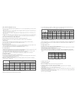
numbers, as shown on the table below.
5) Modify the battery pack to match the setting number in control panel.
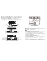
6) Then, modify charger voltage according to the table below to match the setting number on the control board. There are 5
jumpers on the charger board. Please refer to the below table to modify charger voltage.
7) After executing the previous steps, replace the UPS cover. Switch on the battery breaker followed by the input breaker. The UPS
will enter into the Bypass mode. If the UPS is in maintenance Bypass mode, turn the maintenance switch to the
UPS
position
before turning on the system.
13. Changing charging current
1) This operation should only be performed by trained and qualified technicians.
2) Turn off the UPS. If the load could not be cut off, you should remove the cover of maintenance bypass switch on the rear panel
and turn the maintenance switch to the
BPS
position first.
3) Switch off the input breaker and then do the same with the battery breaker.
4) Remove the cabinet cover and disconnect battery wire. Then modify the jumpers on the charger board to set the charging
current (refer to table below). Be careful that the maximum setting should not exceed the charging current acceptable for the
battery.
3.5 Parallel system operation
1. Parallel system installation
If the UPS is only available for single operation, you may skip this section to the next.
1) Install and wire the UPS units according to section 3.5.2 in this manual.
2) Connect the output wires of each UPS to an output breaker or maintenance bypass switch with an output breaker
(sold separately).
3) Connect all output breakers to a maintenance bypass switch with breaker.
4) Each UPS must be connected to its own power bank. In the event a single power bank is used for all the UPS units, it will cause
permanent damage to the equipment.
5) Remove the cover of the parallel share current cable port on the UPS. Connect each UPS one by one with the parallel cable and
share current cable, and then screw the cover back again.
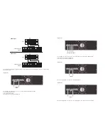
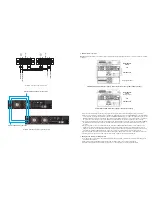
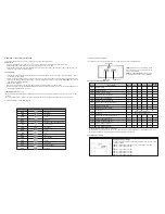
6) Refer to the following wiring diagram.
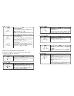
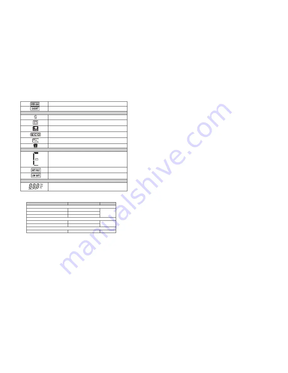
Input and battery voltage information
Battery information
Indicates the battery is charged at 0-25%, 26-50%, 51-75%, and
76-100% of its capacity.
Indicates the input voltage or frequency, or battery voltage.
VAC: input voltage VDC: battery voltage Hz: input frequency
Indicates the battery is not connected.
Low battery and low voltage indicator.
Indicates that the UPS is connected to the mains.
Indicates the battery is in working status.
Indicates the bypass circuit is in working status.
Indicates the ECO mode is enabled.
Indicates the inverter circuit is working.
Indicates the output connector is working properly.
Mode operation information
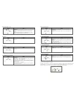
Input and battery voltage information
Battery information
Indicates the load level at 0-25%, 26-50%, 51-75%, and 76-100%
Indicates the battery is charged at 0-25%, 26-50%, 51-75%, and
76-100% of its capacity.
Indicates the input voltage or frequency, or battery voltage.
VAC: input voltage VDC: battery voltage Hz: input frequency
Overload indication.
Indicates the load or the output is short-circuited.
Indicates the battery is not connected.
Low battery and low voltage indicator.
Indicates that the UPS is connected to the mains.
Indicates the battery is in working status.
Indicates the bypass circuit is in working status.
Indicates the ECO mode is enabled.
Indicates the inverter circuit is working.
Indicates the output connector is working properly.
3-3. Audible alarm
3-4. Single UPS operation
1. Turn on the UPS with utility power (On grid/ AC mode)
1) In order for this equipment to operate properly, first you need to make sure that the connection between the UPS and the
power pack is correct. Then set the battery pack breaker to its
ON
position. Next, set the UPS breaker to its
ON
position. At
this point, the fan will start running while the UPS supplies power to the loads via the bypass. This means that the UPS has
begun operating in Bypass mode.
Caution:
To maintain the system reliability, make sure to follow the correct sequence when powering on the equipment.
Note:
When the UPS is in Bypass mode, the output voltage will directly power the loads from utility after you have switched on
the input breaker. In Bypass Mode, the load is not protected by the UPS. To protect your load devices, you should turn on the
UPS as explained below.
Summary of Contents for FDC-106KMR-ISO
Page 17: ......


