47
Model D2424LV Reference Manual (Recording Digital Data)
Digital recording to external digital equipment
Tunes recorded on the D2424LV can be recorded on external digital equipment such as MD, DAT,
CD-R or adat. In order to digital record to external digital equipment, digital signals to be output at
the D2424LV
[DATA OUTPUT]
connector must be set to “
SP DIF
” or “
adat
” (The initial setup is “adat.”)
by the “Setup of digital output” menu in the D2424LV SETUP mode. The currently active program
can be digitally recorded and “Setup of digital outputs” will be common to all programs.
• Connecting external digital equipment
1. Use an optical cable to connect the [DATA OUTPUT] connector of the recorder to the OPTICAL IN (or adat IN)
jack of the external digital equipment.
Set the external equipment input port to “digital” so that digital signals can be input.
Because some digital equipment must be externally synchronized against digital signals, in addition to setting the input
port to “digital,” be sure to refer to the operating manual of any digital equipment to be used.
Depending on the digital signal that is output, the
[DATA OUTPUT]
connector will function as explained below.
SPDIF :Async
SPDIF :Sync
adat :Async
adat :Sync
[D. in ?] setting
[Clock Sel ?]
setting
Int
Auto
Word
Video
clock received
from WORD IN
Ava i l a bl e o n l y
when installing
t h e o p t i o n a l
Model 8346 TC/
SYNC card. If you
t r y t o s e l e c t
“Video,” “Void w/
o 8346” is dis-
played and you
cannot select it.
See the appendix
of the Reference
manual for details.
Regardless of receiving or not
receiving word clock from
WORD IN, the recorder is ref-
erenced to the internal clock.
When the recorder receives
correct digital signals, the
“DIGITAL” indicator lights in
the display.
When receiving word clock
from WORD IN, the recorder
automatically synchronizes to
the incoming clock, while the
“DIGITAL” and “EXT” indica-
tors light in the display.
When receiving word clock
from WORD IN, the recorder
synchronizes to the incoming
clock, while the “DIGITAL” and
“EXT” indicators light in the dis-
play.
Regardless of receiving or not receiving word clock from WORD IN, the recorder synchro-
nizes to the external S/P DIF digital signal. When the recorder receives correct digital signals,
the “DIGITAL” and “EXT” indicators light in the display. When Digital In is set to a SYNC mode,
if you try to select “Clock Sel?” menu, The display will show “Clock Sel D.in!” (indicating that
the clock is set to Digital In!) and the recorder ignores your operation.
no clock
received from
WORD IN
no clock
received from
WORD IN
clock received
from WORD IN
When no word clock is re-
ceived, the recorder is refer-
enced to the internal clock,
while the “EXT” indicator
flashes.
When no word clock is re-
ceived, the “EXT” indicator
flashes showing that the unit
cannot be locked.
OUTPUT
DATA
16 - 9
24 - 17
8 - 1
INPUT
16 - 9
24 - 17
8 - 1
OUTPUT
DATA
16 - 9
24 - 17
8 - 1
INPUT
16 - 9
24 - 17
8 - 1
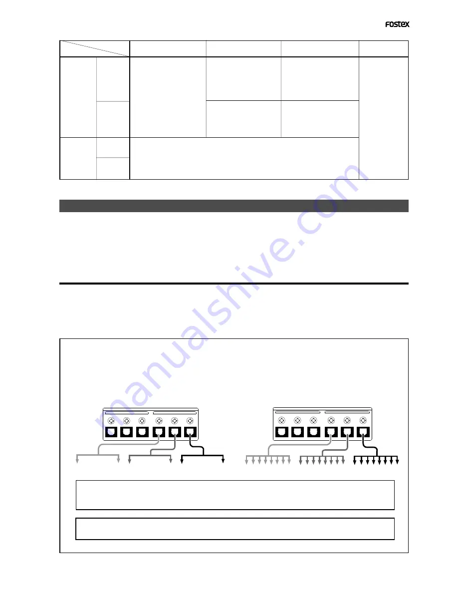
<Notes on interconnecting>
[DATA OUTPUT]
of the D2424LV must be setup for S/P DIF digital signals (optical) or adat digital signals
by the "Setup of digital output" menu in the SETUP mode. Although the connector type is same for both
S/P DIF digital and adat digital signals, their information content is different. Depending on the digital
signal selected, the following signals are output from each output connector.
<At output of S/P DIF digital signals>
<At output of adat digital signals>
Output of tracks 5-6
Output of tracks 3-4
Output of tracks 1-2
Output of tracks 17-24
Output of tracks 9-16
Output of tracks 1-8
<Important!>
Be sure to output a digital signal (S/PDIF or adat) of the same sampling frequency as that used on the
recorder.
<Note>
The [DATA OUTPUT] connectors of the unit does not support 96kHz FS adat digital signals.


