11
Model VM88 Owner’s Manual
< Please remember! >
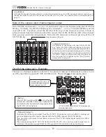
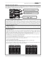
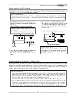
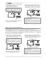
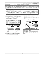
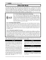
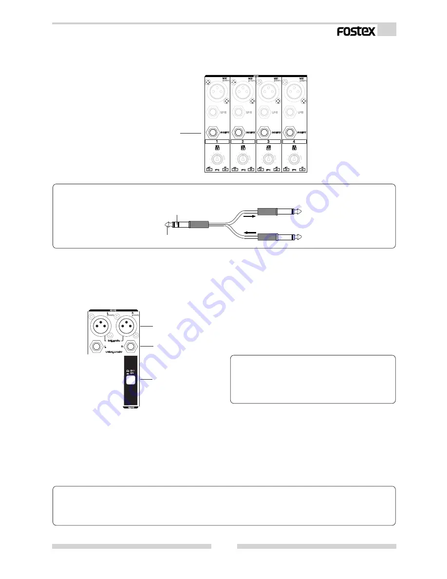
When connecting a compressor/limiter to the INSERT jack, be sure to use the connecting cables shown
below.
To VM88 INSERT jack
To compressor/limiter input jack
To compressor/limiter output jack
TRS phone jacks
TIP: SEND
RING: RETURN
Canon connectors (balanced: 2 HOT)
Phone jacks (unbalanced)
ST OUT ON/OFF switch
(5) DIGITAL IN/OUT jacks (Rear panel)
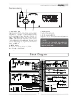
A digital signal (S/P DIF or ADAT) from external digital equipment is input to the DIGITAL IN jack; these signals
can be applied to any input channel. From the DIGITAL OUT jack, mixed signal, which is the same as those
output from the ST OUT L, R connectors can be output in digital (S/P DIF) or the INPUT 1-8 input signals can be
directly output in digital (ADAT) signal. If ADAT is selected, the input signal prior to being affected by the INPUT
fader and EQ can be output digitally.
< Please remember! >
If a digital signal (S/P DIF or ADAT) is to be input to VM88 or a digital signal (S/P DIF or ADAT) is to be output
from the VM88, it will be necessary to setup the system clock and DIGITAL IN or DIGITAL OUT modes.
For details, refer to “Normal mix mode” on page 15 and “Setup mode” on page 33.
< Please remember! >
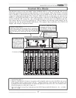
Outputs from the ST OUT L, R connectors can be
switched on/off with the ST OUT ON/OFF switch.
For details, refer to “Normal mix mode” on page
15.
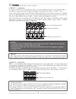
(3) INSERT 1 ~ 4 jacks
INSERT 1-4 jacks are used when a compressor/limiter is applied to the mic input signals into INPUT 1-4, as
shown in the previous connecting example. The in/out are TRS phone jacks and standard input/output levels
are -10dBV.
(4) ST OUT L, R connectors
Balanced output Canon connectors (XLR-3-32 type) and unbalanced output phone jacks are provided for ST
OUT L, R, either of which can be selected depending on the application. Amplifiers and other mixers are
connected here. The standard output level is balanced 4dBu and unbalanced output -10dBV.


