14
Model VM88 Owner’s Manual
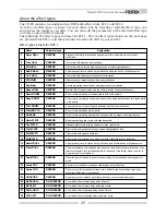
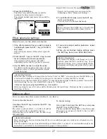
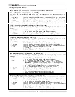
VM88 Initial State
The following explains what to do the first time you use the VM88 directly from the shipping carton.
When the power cable is plugged into the wall outlet and the VM88 POWER is switched on, the VM88
display and the operating panel lamps will become active as shown below.
This is the same as when the CPU is reset by pressing the RESET switch.
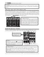
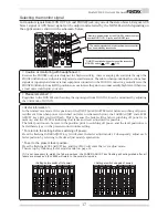
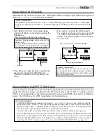
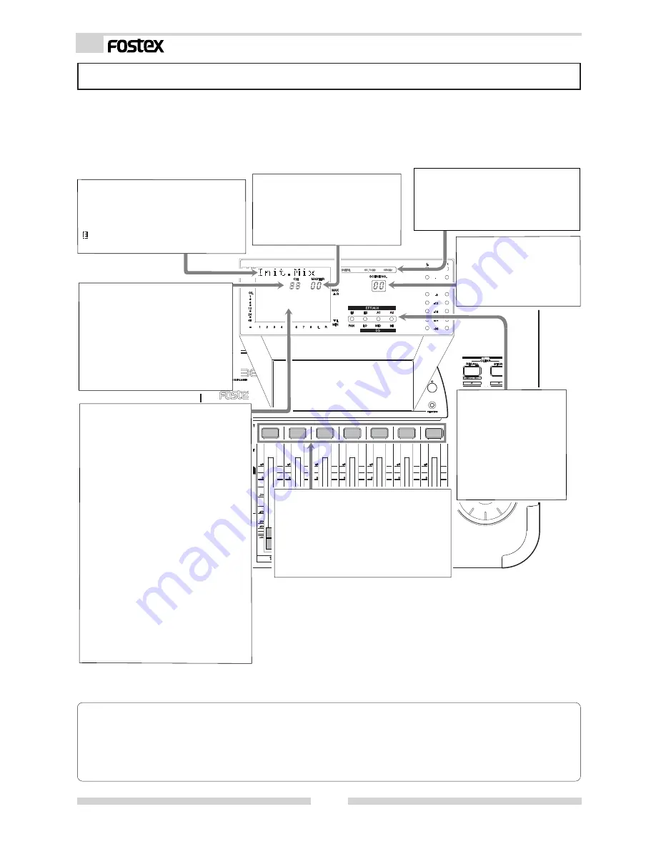
Level display section:
If in any mode except the channel
parameter edit mode and the fader adjust
mode, the signal level input to each INPUT
connector for channels 1 ~ 8 will be
indicated by the prefader. In other words,
the input signal level will be constantly
displayed regardless of the INPUT fader
position. At TRIM knob to adjust the gain
is provided to match the sound source
input for each INPUT for channels 1 ~ 8.
By watching the level display while
adjusting the gain, the most suitable gain
adjustment can be made. Channels L and
R display the signal level which is output
from the STEREO OUT L, R connectors but,
in the initial state, the level meter will not
show any value as the MASTER fader will
be at [MIN]. For both inputs and outputs,
if the signal level reaches [OL] (over load),
the sound will distort and therefore, the
TRIM and INPUT faders should be checked
and adjusted if necessary.
DIGITAL IN status display section:
The DIGITAL IN status will be displayed
and during initial setup [44.1kHz] will
be lit. For details, refer to “Normal mix
mode” on page 15.
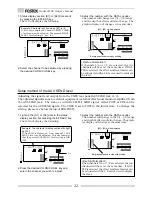
Character display section:
F o l l o w i n g t h e < < F O S T E X > > - >
<<VM88>> display, [Init.Mix] will be
displayed. If the INPUT fader/MAS-
TER fader is manipulated in this state,
will be lit behind the [Init.Mix] dis-
play (Refer to next page).
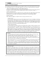
MASTER fader section:
The MASTER fader position is in-
dicated by numbers 00 ~ 99.
The initial setting is [00] which is
the initial mix setting (The fader
[MIN] position).
Scene number display sec-
tion:
The current active scene
number (00 ~ 20) is dis-
played. In the initial set-
ting, [00] will be displayed.
Channel fader display section:
After entering the channel param-
eter edit mode, the INPUT fader
position of the channel selected by
the CH ON/CH SEL key will be in-
dicated by numbers 00 ~ 99.
In the initial state, nothing is dis-
played. For details, refer to [Chan-
nel parameter edit mode] on page
20.
Status indicator:
The dot selected by the
channel parameter edit
mode will light but
nothing lights in the
initial state.
Refer to [Channel pa-
rameter edit mode] on
page 20 for details.
CH ON/CH SEL key:
The channel to be edited can be selected
with this key in the channel parameter
edit mode and, in other modes, each
channel can be switched ON/OFF. In
the initial state, all channels will be in-
dicated as ON and the key LED's will all
light.
< Please remember! >
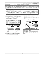
* The scene number of the sber of the ssber of the scene memory which the user can setup are [01] ~
[20] but the preset scene [00] cannot be changed. Refer to page 30 for details on the scene memory.
* If, for some reason, you would like to return the VM88 setting to the factory default figure, refer to
[Reset of VM88] on page 8.


