15
Model VM88 Owner’s Manual
-
OPTICAL
OPTICAL
MAX
MAX
R
L
8
7
6
5
4
3
2
1
48
48
24
24
12
12
6
1
MIN
MIN
R
L
PAN
AN
LO
LO
MID
MID
HI
HI
R
L
SCENE NO.
SCENE NO.
48kHz
48kHz
44.1kHz
44.1kHz
DIGIT
DIGITAL
AL
E1
E1
E2
E2
A1
A1
A2
A2
CH
CH
MASTER
MASTER
PHANT
PHANTOM
OM
MASTER
7/8
5/6
4
3
2
1
-
∞
-40
-30
-20
-10
0
+6
-40
-30
-20
-10
0
+6
-40
-30
-20
-10
0
+6
-40
-30
-20
-10
0
+6
-40
-40
-30
-20
-10
0
+6
-40
-30
-20
-10
0
+6
-40
-30
-20
-10
0
+6
-
∞
-
∞
-
∞
-
∞
-
∞
-
∞
OL
OL
CH ON/CH SEL
CH ON/CH SEL
EFF/AUX
EFF/AUX
EQ
EQ
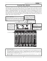
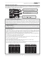
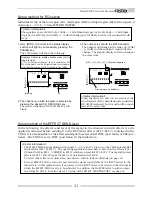
Normal Mix Mode
Level meter:
Displays the STEREO BUSS L,
R output levels.
Normal mix mode means each INPUT fader/MASTER fader is active, and the ON/OFF of each
channel is operational so basic mixing functions can be executed. When the VM88 is in [Initial
state of VM88], as explained in the previous section, if the INPUT fader of the channel to which
a signal is being input (Example: The channel 1 INPUT fader if a sound source is connected to
INPUT 1.) and the MASTER fader is raised, signals will be output from the STEREO OUT L, R jacks
and the DIGITAL OUT connector. Also, if headphones are connected to the PHONES jack, the
same signal will be heard in the headphones. The headphone monitoring sound volume can be
adjusted by the top panel PHONES GAIN knob. Throughout these operation, the VM88 LCD
display will change as explained below.
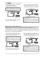
Character display section:
lights following the [Init.Mix] display. This symbol means
"edit" and indicates that the setting had been changed from
the initial state. At this point of operation, the initial state
had been changed by this moving the INPUT and MASTER
faders.
The MASTER fader display section:
The present position to which the
MASTER fader is set will be indicated
by numbers 00 ~ 99. The standard
level setup number is [80].
Level display section:
The input signal level
will be displayed for
channels 1 ~ 4, 5/6 and
7/8 and the output level
in accordance to the
MASTER fader position
indicated by L and R.
Scene number display
section:
The current scene number
will be displayed.
Status display section:
Nothing will light up in the
normal mix mode.
< Useful information !>
* When the MASTER fader is rotated, its position will be digitally indicated in the MASTER fader section
in the display and the sound volume will vary. A digital indication of the INPUT fader position will
be displayed in the [Channel parameter edit mode] explained in the next section. For details, refer to
[Channel parameter edit mode] on page 20.
* The relationship between the actual gain and the INPUT fader and MASTER fader is, 00 = -
∞
, 80dB =
0dB, 99 = +6dB.
All channels are ON.


