background image

Four-Faith Smart Power Technology Co., Ltd.

Chapter 1 Brief Introduction of Product

1.1 General

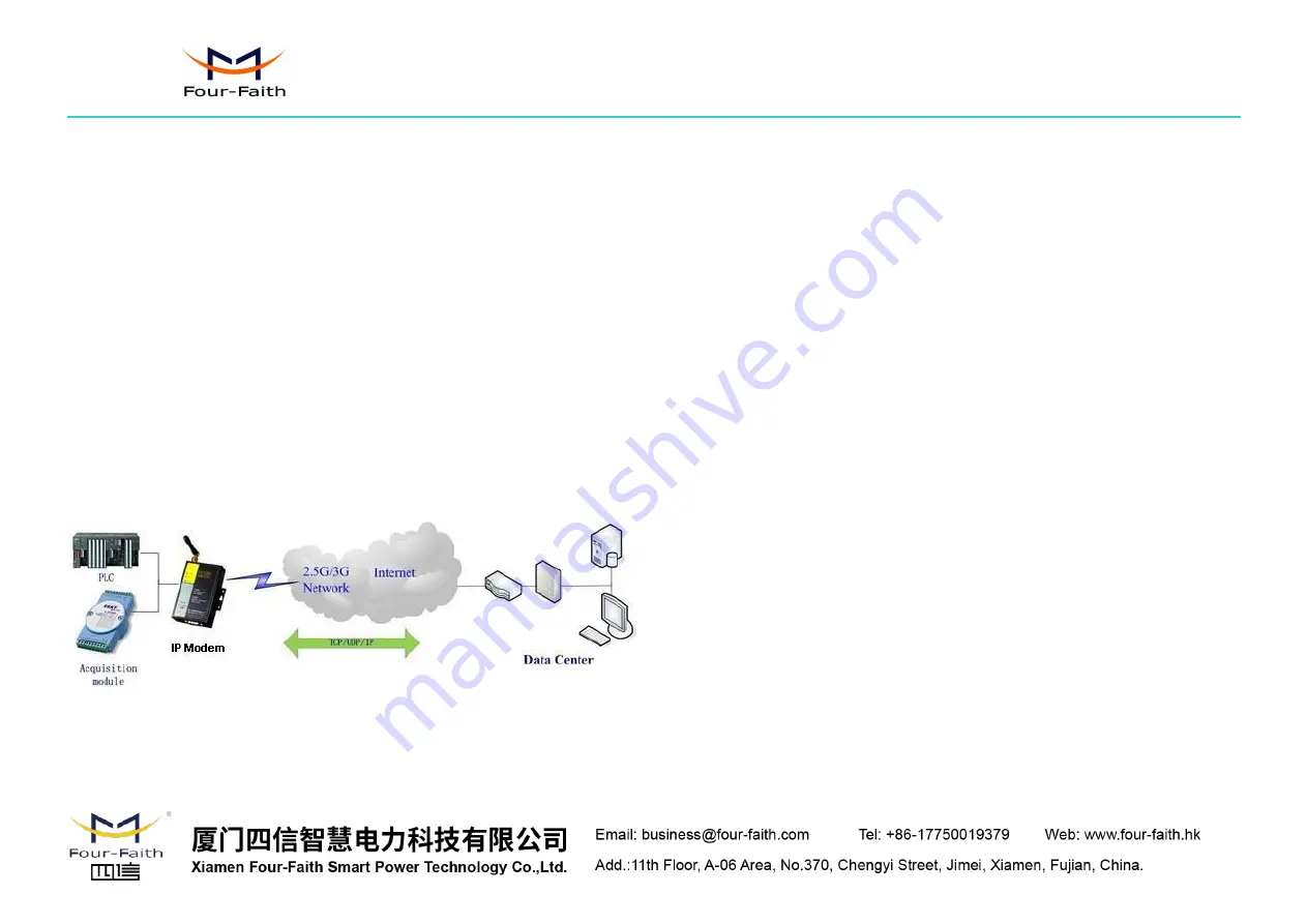
F2103 GPRS IP MODEM is a kind of cellular terminal device that provides data

transfer function by public GPRS network.

It adopts high-powered industrial 16/32 bits CPU and embedded real time

operating system. It supports RS232 and RS485 (or RS422) port that can conveniently
and transparently connect one device to a cellular network, allowing you to connect to
your existing serial devices with only basic configuration.

It has been widely used on M2M fields, such as intelligent transportation, smart

grid, industrial automation, telemetry, finance, POS, water supply, environment
protection, post, weather, and so on.

1.2 Features and Benefits

Design for Industrial Application

High-powered industrial cellular module

High-powered industrial 16/32 bits CPU

Support low-consumption mode, including sleep mode, scheduled online/offline
mode, scheduled power-on/power-off mode(optional)

Housing: iron, providing IP30 protection.

Power range: DC 5~35V

Stability and Reliability

Support hardware and software WDT

Support auto recovery mechanism, including online detect, auto redial when
offline to make it always online

RS232/RS485/RS422 port: 15KV ESD protection

SIM/UIM port: 15KV ESD protection

Power port: reverse-voltage and overvoltage protection

Antenna port: lightning protection(optional)

Standard and Convenience

Support standard RS232 and RS485(or RS422) port that can connect to serial
devices directly

Support intellectual mode, enter into communication state automatically when
powered

Provide management software for remote management

Support several work modes

Convenient configuration and maintenance interface

High-performance

Support TCP server and support multi TCP client connection(optional)

Support double data centers, one main and another backup

Support multi data centers and it can support 5 data centers at the same time

Support multi online trigger ways, including SMS, ring and data. Support link
disconnection when timeout

Summary of Contents for F2103

Page 1: ...Four Faith Smart Power Technology Co Ltd F2103 GPRS IP MODEM USER MANUAL ...

Page 2: ... 2 2 Encasement List 6 2 3 Installation and Cable Connection 6 2 4 Power 7 2 5 Indicator Lights Introduction 8 Chapter 3 Configuration 9 3 1 Configuration Connection 9 3 2 Configuration Introduction 9 3 3 Run the configure Tool IP Modem Configure exe 9 3 4 Re power IP MODEM 10 3 5 Configuration 10 3 5 1 Data Service Center Settings 10 3 5 2 IP MODEM Settings 12 3 5 3 Other Settings 16 3 6 Function...

Page 3: ...offline mode scheduled power on power off mode optional Housing iron providing IP30 protection Power range DC 5 35V Stability and Reliability Support hardware and software WDT Support auto recovery mechanism including online detect auto redial when offline to make it always online RS232 RS485 RS422 port 15KV ESD protection SIM UIM port 15KV ESD protection Power port reverse voltage and overvoltage...

Page 4: ...m GSM1800 1900 30dBm RX sensitivity 107dBm Hardware System Item Content CPU Industrial 16 32 bits CPU FLASH 1MB Extendable SRAM 512KB Extendable Interface Type Item Content Serial 1 RS232 port and 1 RS485 orRS422 port 15KV ESD protection Data bits 5 6 7 8 Stop bits 1 1 5 2 Parity none even odd space mark Baud rate 110 230400 bps Indicator Power ACT Online Antenna Standard SMA female interface 50 o...

Page 5: ...umption 250mA 12V Physical Characteristics Item Content Housing Iron providing IP30 protection Dimensions 91x58 5x22 mm Weight 205g Environmental Limits Item Content Operating Temperature 25 65ºC 13 149 Extended Operating Temperature 30 75ºC 22 167 Storage Temperature 40 85ºC 40 185 Operating Humidity 95 Non condensing ...

Page 6: ...ptional RS485 data cable 1 optional Manual CD 1 Certification card 1 Maintenance card 1 2 3 Installation and Cable Connection Dimension unit mm 58 5 35 28 28 22 8 25 Ф3 Ф5 4 Installation of SIM UIM card Firstly power off the IP MODEM and press the out button of the SIM UIM card outlet with a needle object Then the SIM UIM card sheath will flick out at once Put SIM UIM card into the card sheath Pay...

Page 7: ... cable into the DB9M interface of IP MODEM and connect the other end with user s device The signal connection of the RS232 data cable is as follows The signal connection of the RS485 data cable is as follows 2 4 Power The power range of the IP MODEM is DC 5 35V Warning When we use other power we should make sure that the power can supply power above 4W We recommend user to use the standard DC 12V ...

Page 8: ...he IP MODEM provides three indicator lights Power ACT Online Indicator Light State Introduction Power ON IP MODEM is powered on OFF IP MODEM is powered off ACT BLINK Data is communicating OFF No data Online ON IP MODEM has logged on network OFF IP MODEM hasn t logged on network ...

Page 9: ...re configuration with extended AT command you should make IP MODEM enter configure state The steps how to make IP MODEM enter configure state please refer to appendix The following describes how to configure IP MODEM with the configure software tool At the same time it gives out the corresponding AT command of each configuration item 3 3 Run the configure Tool IP Modem Configure exe The Serial Par...

Page 10: ...he parameters related to Data Service Center DSC Data Center Number IP MODEM support two Data Service Center methods to transmit data Main and Backup IP MODEM always tries to connect with the Main DSC If fails to connect with Main DSC it will connect with Backup DSC at once Note If no Backup DSC exists please configure the Backup DSC same as Main DSC Multi Data Service Center IP MODEM can connect ...

Page 11: ...mmand of the Backup DSC IP address or domain AT IPSEC xxx xxx The IP address or domain name AT command of the Backup DSC port AT PTSEC xxx xxx The port value Multi DSC Configuration When Data Center Number is greater than 1 this setting is valid For example setting the Data Center Number as 3 Main Center 2nd Center 3rd Center work as these three DSC AT Command of the 2 5 DSC IP address or domain n...

Page 12: ...aa bbb ccc ddd The DNS server IP address must be IP address AT command of Backup Center DNS server AT DNSSV2 aaa bbb ccc ddd aaa bbb ccc ddd the DNS server IP address Center 2 5 DNS Server When the IP MODEM work in Multi Data Service Center method and the centers use domain name 2 5 DNS server is used to resolve center 2 5 correspondingly AT command of 2 5 DNS Server AT DNSSVRn aaa bbb ccc ddd n i...

Page 13: ...nd heartbeat string Data transmission with TCP protocol AT command AT MODE xxxx xxxx one of the above workmode Trigger Type Normally IP MODEM always keeps online and always be ready for data transmission But in some circumstances it s important to reduce wireless data flow To realize this function the software can makes IP MODEM into sleep state in idle time When there is application data to trans...

Page 14: ...mode Communication Baudrate 110 110 bps 300 300 bps 600 600 bps 1200 1200 bps 2400 2400 bps 4800 4800 bps 9600 9600 bps 14400 14400 bps 19200 19200 bps 38400 38400 bps 56000 56000 bps 57600 57600 bps 115200 115200 bps AT Command AT IPR xxx xxx one of the above baudrate Auto Back To Main Server 0 No 1 Yes This item is only valid when you set Data Center Number as 1 In this mode IP MODEM will switch...

Page 15: ...IM card phone number Bytes Interval The time interval used to determine whether the serial data frame transmission has completed IP MODEM will send the serial data to the center when two bytes transmit time interval larger than this item value AT Command AT BYTEINT xxx xxx bytes interval time value millisecond Custom Register String This item is only valid when the WorkMode is TCST It s the self d...

Page 16: ...items When IP MODEM fail to connect to the center with the configured Retry Time It will sleep Reconnect Time Interval time then start next retry Connect Retry Times AT Command AT RETRY xxx xxx times try to connect to the center Reconnect Time Interval AT Command AT RDLWT xxx xxx the sleep time until next retry Transfer meanning 0 Yes enable transfer meaning 1 No disable transfer meaning This item...

Page 17: ...s point name AT Command of Username AT USERNAME xxx xxx username AT Command of Password AT PASSWORD xxx xxx password AT Command of Call Center AT CENT xxx xxx call center phone number of ISP SMS Center Your local SMS center number AT Command AT SMSC xxx xxx your local SMS center number Heartbeat Interval Time interval sent heartbeat packet unit is second AT Command AT POLLTIME xxx xxx heartbeat pa...

Page 18: ... it will connect to the center AT Command AT SMSDPSWD xxx xxx SMS content to trigger IP MODEM online Data Trigger Password This item is valid only when the Trigger Type is DATA or MIXD IP MODEM will keeps in idle state until it receives the trigger on data then it will connect to the center It will return to the idle state when receives trigger off data AT Command of Data Trigger On Password AT DO...

Page 19: ... 3 6 Functions Clear Output Clear the output information Version Display Show the software and hardware version Signal Value Display current wireless signal value Factory setting Restore to factory settings Show Config Show current IP MODEM settings Show Baudrate Display the communication baudrate Auto Detect Simple way to determine whether IP MODEM work fine Save Output Save the output info to a ...

Page 20: ... MODEM Communication This state is used as a common serial communication tool Reboot Device Enter Communication State This function button is used to reboot IP MODEM and make the software switch to Communication state Appendix The following steps describe how to make IP MODEM enter configure state with the Windows XP Hyper Terminal 1 Press Start Programs Accessories Communications Hyper Terminal 2...

Page 21: ...the correct COM port which connect to IP MODEM choose OK 4 Configure the serial port parameters as following choose OK Bits per second 115200 Data bits 8 Parity None Stop bits 1 Flow control None 5 Complete Hyper Terminal operation It runs as following ...

Page 22: ... Co Ltd 6 Re power IP MODEM put mouse focus on the Hyper Terminal and press s key continuously until IP MODEM enter configure state as following 7 IP MODEM has entered configure state you can configure the parameters through AT command ...

Reviews: