User Manual
Xiamen Four-Faith Communication Technology Co.,Ltd.
Page 12 of 42
Add
:
J1-J3,3
rd
Floor,No.44,GuanRiRoad,SoftWare Park,XiaMen .361008.China
http
:
//www.fourfaith.com Tel
:
+86 592-6300326 6300325 6300324 Fax
:
+86 592-5912735
58.5
35
28
28
22
8
25
Ф
3
Ф
5
4
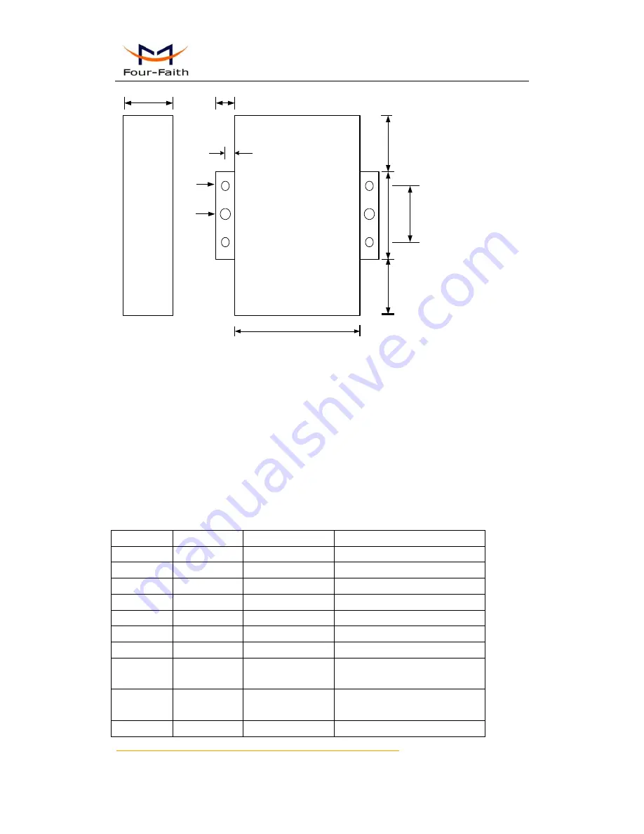
Figure 2-1 Installation Chart
Installation of SIM/UIM card:
Firstly power off the IP MODEM, and press the out button of the SIM/UIM card outlet with a
needle object. Then the SIM/UIM card sheath will flick out at once. Put SIM/UIM card into the
card sheath (Pay attention to put the side which has metal point outside), and insert card sheath
back to the SIM/UIM card outlet.
Warning:
Forbid to install SIM/UIM card when powered!
Installation of antenna:
Screw the SMA male pin of the antenna to the female SMA outlet of the IP MODEM tightly.
Warning: The antenna must be screwed tightly, or the signal quality of antenna will be influenced!
User Interface Signal Definition
Pin Number
Signal Name
Default Function
Extensible Function
1
PWR
Power input anode
N/A
2
GND
Power Ground
N/A
3
GND
Power Ground
N/A
4
RX
RS232 RX
N/A
5
TX
RS232 TX
N/A
6
A
RS485 anode
Reserved compatible DTR
7
B
RS485 cathode
Reserved compatible DSR
8
IO1
GPIO
Reserved compatible RTS and
RS232 RX (TTL logic level)
9
IO2
GPIO
Reserved compatible CTS and
RS232 TX (TTL logic level)
10
IO3
GPIO
Reserved compatible DCD


