background image

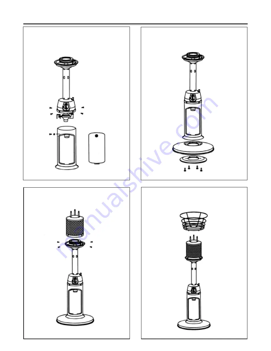
Assembly Process

7

Step 2- Attach weight to base, using four 

bolts.

Step  1  -  Attach  post  onto  housing,                 

using  four  bolts  and  washers.  Keep  the 

access panel open.

Step 3 - Attach emmitter assembly to post 

using four bolts and washers.

Step 4 - Insert ends of wire guard into holes 

in the post flange.

Summary of Contents for FM35PHLP

Page 1: ...tween 8 00 AM and 5 00 PM Eastern time Monday through Friday or email us at saleshelp sureheat com YOUR SAFETY 1 Read this Manual before attempting to assemble or operate your heater 2 Follow safety i...

Page 2: ...al Safety Instructions Components Hardware Assembly Process Gas Requirement Pre Operation Leak Testing Operation Care Maintenance Troubleshooting Warranty Table of Contents 3 5 6 7 8 8 10 11 12 13 14...

Page 3: ...sed extensively throughout this manual Always heed these precautions as they are essential when using any mechanical or fueled equipment RECOGNIZE SAFETY SYMBOLS WORDS AND LABELS WARNING indicates a p...

Page 4: ...lating air passageway of the appliance be kept clean FOR YOUR SAFETY If you smell gas 1 Shut off gas to the appliance 2 Extinguish open flame 3 If odor continues immediately call your gas supplier and...

Page 5: ...sed in compliance with local ordinances and codes or with ANSI NFPA 58 Turn off propane when not in use DANGER EXPLOSION FIRE HAZARD Never store propane near high heat open flames pilot lights direct...

Page 6: ...Reflector 3 Washer 4 Emitter 5 Wire guard 6 Access panel 7 Base 8 Cast iron ring weight 9 M6x20 bolts 4 pcs 10 3 16 Stainless bolts 4 pcs and washers 4 pcs 11 Post with burner assembly 12 3 16 Stainl...

Page 7: ...base using four bolts Step 1 Attach post onto housing using four bolts and washers Keep the access panel open Step 3 Attach emmitter assembly to post using four bolts and washers Step 4 Insert ends o...

Page 8: ...bolts then attach reflector to emitter assembly using three cap nuts Step 6 Rotate regulator toward opening in housing Line up threads on gas cylinder with those on the regulator Insert and rotate cyl...

Page 9: ...ust be constructed and marked in accordance with the specifications for L P gas cylinders of the U S Department of Transportation DOT or the National Standard of Canada CAN CAS B339 Cylinders Spheres...

Page 10: ...and repeat steps 1 3 3 Wash off soapy solution with cold water and towel dry Check all gas supply fittings before each use and each time the gas supply cylinder is connected to the regulator Have a qu...

Page 11: ...the air in the line This can take up to 10 seconds 9 To start the burner rotate the Control Knob in a clockwise direction and stop at the desired temperature position 11 BEFORE TURNING GAS SUPPLY ON 1...

Page 12: ...ff but the pilot light will remain on 2 To turn off the pilot light depress the control knob and rotate to the OFF position WARNING FOR YOUR SAFETY Heater will be hot after use Handle with extreme car...

Page 13: ...rous condition which can cause a fire to occur behind the valve panel thereby damaging the heater and making it unsafe to operate We recommend you check the heater and remove any spiders insects and w...

Page 14: ...t Clean dirt from around pilot Connection between gas valve and pilot assembly is loose Tighten connection and perform leak check Thermocouple is not operating correctly Replace thermocouple Burmer wo...

Page 15: ...uct to temperatures above its rated specifications which can cause considerable warping disassembly including removal of the product from a built in installation damage resulting from accident alterat...

Reviews: