Section H
Page 5
Vista 248/268 Owners Manual
03/00
H - 6
DOCKSIDE OPERATION
If any abnormalities appear during dockside op-
eration, DISCONNECT the system immediately
to prevent electric shock hazards! Have the
boats electrical system and the shoreside recep-
tacles checked as soon as possible.
A. Shore Power Connections
To prevent electric shock hazards, use only equ-
ipment with approved three wire electrical plug
connections. Be sure each item being used has
been tested and is free of electrical shorts and
ground faults.
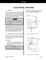
Fifty foot, ten gauge, three wire, shore power cords are
provided with dockside wiring. The shore power cords
on 60 Hertz systems have 30 amp twistlock-type con-
nectors. This connector is approved by National Marine
Manufacturers Association and the American Boat and
Yacht Council.
Some marinas are not equipped with approved twistlock-
type receptacles. An adaptor is available from Four
Winns® which converts the twistlock shore plug to a three
wire grounded household type plug. Use only an ap-
proved adaptor when an adaptor is necessary.
DO NOT use a two-wire adaptor to connect to a
three-wire system. These adapters do not pro-
vide adequate grounding.
Shore power connection procedure is as follows:
1. Turn off the boats main breaker switch before con-
necting or disconnecting the shore power cable.
2. Connect shore power cable at the boat first, then
connect it to dockside shore power outlet.
NOTICE
Always connect the cord to the power inlet recep-
tacle of the boat before making connections to
the shore power source.
Stereo - The stereo has a separate switch on the unit
and is protected by a circuit breaker labeled STEREO
on the 12 volt cabin panel of the 248/268.
Sump Pump - A sump pump is used to discharge water
from the shower and sink drains overboard. It is in-
stalled on all Vistas. The sump pump has a float switch
which will activate the pump when the water level rises
in the sump. This pump is protected by the SUMP fuse
located at the helm.
If the boat is equipped with a grey water system, the
water from the shower and sinks is pumped into a hold-
ing tank instead of overboard.
H - 5
120 (220) VOLT ELECTRICAL SYSTEM
The boat is equipped with 30 amp, 120 volt, 60 Hertz (or
15 amp, 220 volt, 50 Hertz) AC electrical wiring. When
the boat is connected to a shore power outlet, the AC
system supplies electrical power to the following items:
battery charger, refrigerator, water heater, range, mi-
crowave, outlets, and air conditioning. The dockside
system uses three-wire, color-coded circuitry. The black
or hot wire is the ungrounded current carrying conduc-
tor. The white or neutral wire is the grounded current
carrying conductor. The green wire, referred to as the
equipment ground, is a grounded conductor, and un-
der normal conditions is not a current carrying wire. The
neutral wires are connected together at a buss bar. The
equipment grounds are similarly connected together at
another buss bar. Each hot wire is connected to, and
protected by, a circuit breaker in the distribution box.
The standard dockside system has a main circuit breaker
which protects the overall distribution network. The 248/
268s MAIN dockside inlet is on the port side of the
deck. The MAIN circuit breaker protects both the hot
and neutral input leads. This breaker is sensitive. The
resulting power surge which occurs when connecting
the shore power cord may cause the MAIN breaker to
trip. To avoid this power spike, turn off the MAIN break-
er before plugging in the shore power cord. Securely
connect the power inlet of the boat and the shore power
receptacle. Once the shore power is securely con-
nected, turn the MAIN breaker back on. If the connec-
tion is broken and later re-secured, the circuit breaker
may trip. Connections must be secure for uninterrupted
dockside service.
Summary of Contents for 248 Vista
Page 1: ......
Page 35: ......
Page 36: ......
Page 37: ......
Page 38: ......
Page 39: ......
Page 40: ......
Page 43: ......
Page 44: ......
Page 45: ......
Page 46: ......
Page 47: ......
Page 48: ......
Page 49: ......
Page 50: ......
Page 51: ......
Page 52: ......
Page 53: ......
Page 54: ......
Page 81: ...Section J Page 10 Vista 248 268 Owner s Manual 03 00 FIGURE J9 248V HEAD...
Page 82: ...Section J Page 11 Vista 248 268 Owner s Manual 03 00 FIGURE J10 248 FRESH WATER SYSTEM 1 OF 2...
Page 83: ...Section J Page 12 Vista 248 268 Owner s Manual 03 00 FIGURE J11 248 FRESH WATER SYSTEM 2 OF 2...
Page 84: ...Section J Page 13 Vista 248 268 Owner s Manual 03 00 FIGURE J12 248V WASTE SYSTEM 1OF 2...
Page 88: ...Section J Page 17 Vista 248 268 Owner s Manual 03 00 FIGURE J16 268V HEAD...
Page 89: ...Section J Page 18 Vista 248 268 Owner s Manual 03 00 FIGURE J17 268 FRESH WATER SYSTEM 1 OF 2...
Page 90: ...Section J Page 19 Vista 248 268 Owner s Manual 03 00 FIGURE J18 268 FRESH WATER SYSTEM 2 OF 2...
Page 91: ...Section J Page 20 Vista 248 268 Owner s Manual 03 00 FIGURE J19 268V WASTE SYSTEM 1 OF 2...
Page 92: ...Section J Page 21 Vista 248 268 Owner s Manual 03 00 FIGURE J20 268V WASTE SYSTEM 2 OF 2...
Page 99: ...Section L Page 4 Vista 248 268 Owner s Manual 03 00 Figure L7 248 268V Air Conditioning System...
Page 112: ......
Page 113: ......
Page 114: ......
Page 115: ......
Page 116: ......
Page 117: ......
Page 118: ......
Page 119: ......
Page 127: ......
Page 128: ......
Page 129: ......
Page 130: ......
Page 131: ......
Page 152: ......
Page 153: ......
Page 154: ......
Page 155: ......
Page 156: ......
Page 157: ......
Page 158: ......
Page 167: ......


