Section I
Page 3
Vista 248/268 Owner’s Manual
03/00
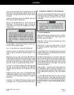
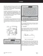
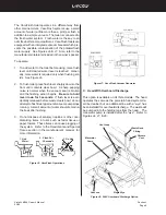
The gauge readings will also vary with the trim angle of
the boat. When sitting at a dock and the boat is nearly
level, the fuel gauge will register accurately. Refer to
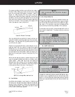
Figure I3. When boating, the trim angle of the boat
changes and affects the gauge readings. Under these
conditions, the fuel sender will register “full” for the first
few hours of running time until the fuel level drops below
the 3/4 or 1/2 mark. This is caused by the angle of the
fuel in the tank as shown in Figure I4.
Figure I4: Effects of Trim Angle
It is very important to keep track of hours and fuel con-
sumption to obtain an average gallon per hour consump-
tion figure. This will prevent any problems with running
out of fuel on the water.
Dealers are equipped with some general figures on con-
sumption which can be used as a guide until specific
information on your boat is determined. Because of boat-
ing conditions, speed, weight and other factors common
to your situation, fuel consumption will vary between your
boat and consumption figures developed by Four
Winns®.
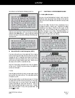
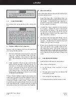
When the fuel gauge begins to register below the “full”
mark, the gauge readings will drop much faster until it
reads” empty”. When this occurs, the trim angle has
affected the sender reading. When the gauge registers
“empty”, the sender has bottomed out and there may be
3 to 4 gallons of fuel in the tank. See Figure I5.
G. Fuel Filters
Fuel filters are installed on each engine. Filters should
be cleaned or changed frequently to assure an adequate
supply of fuel to the engine. Refer to the engine manual
for additional information. The engine manual is included
in the owner’s information packet.
Figure I5: Trim Angle Effect with Low Fuel
NOTICE
OMC canister-type filters should be changed
annually.
H. Gas Vapor Detector
A gas vapor detector is optional on 248/268 Vista model.
The gas vapor detector will monitor the engine compart-
ment and notify the operator of an accumulation of gaso-
line vapors. The operator must take immediate action
upon warning to avoid the possibility of an explosion.
The sensing unit is usually mounted towards the rear of
the engine compartment. The alarm unit is mounted at
the dash.
Always personally inspect the engine compart-
ment and sniff for fuel vapors before starting the
engine. Remember, a gas vapor detector is a
mechanical device. DO NOT rely exclusively
on its operation.
I.
Use and Maintenance
DO NOT let the odor of gasoline go unchecked.
If the odor of gasoline is noted, DO NOT START
ENGINE. If engine is running, SHUT OFF EN-
GINE, ELECTRICAL AND HEAT GEN-
ERATING EQUIPMENT. Investigate and cor-
rect the situation immediately! Have all passen-
gers put on personal flotation devices and keep
fire extinguishers at hand until the situation is
resolved.
Avoid serious injury or death from fire or ex-
plosion resulting from leaking fuel. Inspect sys-
tem for leaks at least once a year.
If areas are found within the fuel system that appear ques-
tionable, have a qualified marine technician inspect the
system. A thorough fuel system examination should be
made by an experienced marine technician at least once
a year.
Summary of Contents for 248 Vista
Page 1: ......
Page 35: ......
Page 36: ......
Page 37: ......
Page 38: ......
Page 39: ......
Page 40: ......
Page 43: ......
Page 44: ......
Page 45: ......
Page 46: ......
Page 47: ......
Page 48: ......
Page 49: ......
Page 50: ......
Page 51: ......
Page 52: ......
Page 53: ......
Page 54: ......
Page 81: ...Section J Page 10 Vista 248 268 Owner s Manual 03 00 FIGURE J9 248V HEAD...
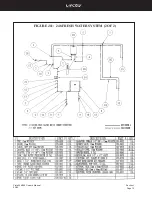
Page 82: ...Section J Page 11 Vista 248 268 Owner s Manual 03 00 FIGURE J10 248 FRESH WATER SYSTEM 1 OF 2...
Page 83: ...Section J Page 12 Vista 248 268 Owner s Manual 03 00 FIGURE J11 248 FRESH WATER SYSTEM 2 OF 2...
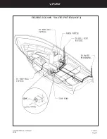
Page 84: ...Section J Page 13 Vista 248 268 Owner s Manual 03 00 FIGURE J12 248V WASTE SYSTEM 1OF 2...
Page 88: ...Section J Page 17 Vista 248 268 Owner s Manual 03 00 FIGURE J16 268V HEAD...
Page 89: ...Section J Page 18 Vista 248 268 Owner s Manual 03 00 FIGURE J17 268 FRESH WATER SYSTEM 1 OF 2...
Page 90: ...Section J Page 19 Vista 248 268 Owner s Manual 03 00 FIGURE J18 268 FRESH WATER SYSTEM 2 OF 2...
Page 91: ...Section J Page 20 Vista 248 268 Owner s Manual 03 00 FIGURE J19 268V WASTE SYSTEM 1 OF 2...
Page 92: ...Section J Page 21 Vista 248 268 Owner s Manual 03 00 FIGURE J20 268V WASTE SYSTEM 2 OF 2...
Page 99: ...Section L Page 4 Vista 248 268 Owner s Manual 03 00 Figure L7 248 268V Air Conditioning System...
Page 112: ......
Page 113: ......
Page 114: ......
Page 115: ......
Page 116: ......
Page 117: ......
Page 118: ......
Page 119: ......
Page 127: ......
Page 128: ......
Page 129: ......
Page 130: ......
Page 131: ......
Page 152: ......
Page 153: ......
Page 154: ......
Page 155: ......
Page 156: ......
Page 157: ......
Page 158: ......
Page 167: ......

