Owner’s Manual Page 66
Control Systems - Section F
F - 1 GENERAL
Control systems permit operation of the engine’s
throttle and shift mechanisms. Typically, they consist
of three major components; the control, the throttle
and shift cables. Models with an electronic binnacle
control consist of the control head, electronic control
units (ECUs), and actuators.
The 358 Vista
®
stern drive models are equipped with
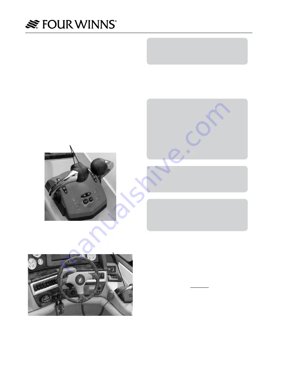
dual engine electronic binnacle con trol with trim. The
inboard models are also equipped with an electronic
binnacle con trol (without trim). See Figures F-1 and
F-2. The left lever controls the port engine and the
right lever controls the starboard engine. Moving the
lever forward will shift the drive into forward. Moving
it aft will shift the drive into reverse. Moving the lever
further will increase engine speed.
Port & Stbd Trim/Tilt Switches
(Stern Drive Only)
Figure F1: Dual Engine Electronic Binnacle Control
Figure F2: Stern Drive / Inboard Helm Station
NOTICE
Allow the engine to warm up before engaging
the shift control. Monitor all instruments while
engine is idling during warm-up.
F - 2 CONTROL OPERATION
A. General
NOTICE
The control information included in this section
is general only. For specific operation of the
controls on your boat, refer to the control
manufacturer’s literature included in your
owner’s packet. Ensure you completely
understand the operation of the controls before
operating your boat. Also consult your dealer
should any questions arise regarding the
operation of the control unit.
NOTICE
If your boat is equipped with a non-OEM
remote control system, ask your dealer how to
properly operate it.
NOTICE
Reduce throttle as soon as motor starts. Do
not run a cold motor any faster than necessary
to keep motor from stalling. Do not exceed
2000 RPM in NEUTRAL.
During the general operation of a twin engine boat,
it is advantageous for both engines to be operated at
the same engine speed (rpm). This reduces noise and
vibra tion, and can increase propulsion system effi
-
ciency. Setting the throttles so the engines are running
at the same rpm (synchro nized) can be done by
engine sounds or by an engine synchronizer gauge.
Attempting to syn chro nize the engines solely by using
tachometer read ings or manually controlling the
throttle lever placement will generally not be effective.
Please note however with the electronic dual binnacle
control engine synchronization is made easier without
the need for engine synchronizer gauge. When the
engines are in proper syn chronization, the throttle
levers may not neces sarily be in the same position.
Control Systems
Dual Engine Electronic
Binnacle Control
Summary of Contents for 358 VISTA
Page 1: ...3 5 8 V I S T A O W N E R S M A N U A L 0 9 0 2 8 2 2 0 7 ...
Page 2: ......
Page 4: ...Table of Contents Owner s Manual Page 1 Table of Contents ...
Page 5: ...Owner s Manual Page 2 Table of Contents ...
Page 6: ...Table of Contents Owner s Manual Page 3 ...
Page 7: ...Owner s Manual Page 4 Table of Contents ...
Page 8: ...Table of Contents Owner s Manual Page 5 ...
Page 9: ...Owner s Manual Page 6 Table of Contents ...
Page 10: ...Table of Contents Owner s Manual Page 7 ...
Page 11: ...Owner s Manual Page 8 Table of Contents ...
Page 51: ...Owner s Manual Page 47 Warranty and Service Section D ...
Page 53: ...Owner s Manual Page 49 Warranty and Service Section D ...
Page 55: ...Owner s Manual Page 51 Warranty and Service Section D ...
Page 77: ...Owner s Manual Page 74 Steering Systems Section G Figure G 5 Inboard Propulsion System ...
Page 78: ...Owner s Manual Page 75 Steering Systems Section G Figure G 6 Tie Bar 45 Tiller Arm Assembly ...
Page 88: ...Owner s Manual Page 85 Electrical Systems Section H Figure H 3 358V SD GENERATOR 1 0F 5 ...
Page 90: ...Owner s Manual Page 87 Electrical Systems Section H FIGURE H 5 358V SD GENERATOR 3 0F 5 ...
Page 91: ...Owner s Manual Page 88 Electrical Systems Section H FIGURE H 6 358V SD GENERATOR 4 0F 5 ...
Page 92: ...Owner s Manual Page 89 Electrical Systems Section H FIGURE H 7 358V SD GENERATOR 5 0F 5 ...
Page 95: ...Owner s Manual Page 92 Electrical Systems Section H FIGURE H 10 358V IB GENERATOR 3 0F 4 ...
Page 96: ...Owner s Manual Page 93 Electrical Systems Section H FIGURE H 11 358V IB GENERATOR 4 0F 4 ...
Page 210: ...Owner s Manual Page 153 Service Log Service Log ...
Page 211: ...Owner s Manual Page 154 Service Log Service Log ...
Page 212: ...Owner s Manual Page 155 Service Log Service Log ...
Page 213: ...Owner s Manual Page 156 Service Information Service Information ...
Page 230: ...Electrical Schematics Owner s Manual Page 227 358 VISTA AC DC PANEL ASSEMBLY 1 of 4 ...
Page 231: ...Electrical Schematics Owner s Manual Page 228 358 VISTA AC DC PANEL ASSEMBLY 2 of 4 ...
Page 232: ...Electrical Schematics Owner s Manual Page 229 358 VISTA AC DC PANEL ASSEMBLY 3 of 4 ...
Page 233: ...Electrical Schematics Owner s Manual Page 230 358 VISTA AC DC PANEL ASSEMBLY 4 of 4 ...
Page 256: ......
Page 257: ... ...


