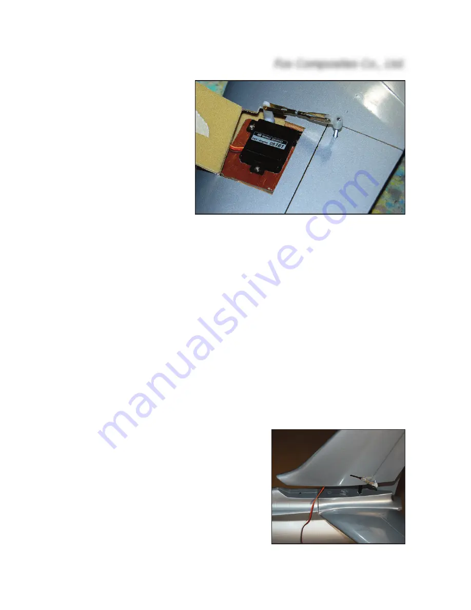
Now thread these holes, right
thru' the elevators, using an M3
tap. Sand both ends of the
threaded rods flat, and screw
on the plastic adapters pro-
vided. Screw them into the
tapped holes until the upper
end is flush with the top surface
of the elevators. The M3 rods
must now be secured in place,
by applying glue through the
open (root) end of the eleva-
tors. Apply one drop of thick CA
and, when cured, add some 30
minute epoxy and micro-bal-
loons mixture.
Make up the linkages between the servo and elevator horns, using M2 or 2 x 56 clevises and
threaded rods. The linkages will need to be approx. 45mm long, clevise pin-to-pin. Fit the clevise
on the servo arm as close to the servo centre as possible, and the clevise on the elevator horn as
far out from the elevator as possible - to maximise the mechanical advantage, whilst still obtain-
ing the necessary maximum elevator throws of 10 - 11mm up and down. When the linkages are
finally adjusted the servo hatches can be held closed with 3 small strips of clear tape. It is not nec-
essary to secure them with screws. Some small scraps of very thin ply or fibreglass sheet glued
inside the edges of the servo bays keep the hatches flush with the wing skin.
IMPORTANT
: Do NOT use ball-joints or ball-links on the plastic horn adapters. They will cause
twisting, and almost certain flutter ! This also applies to the aileron and rudder linkages.
The servo extension cables should be passed thru' 2 separate small holes drilled in the bottom sur-
face of the centre-section, as close to the fuselage sides as possible to keep them away from the
thrust-tube, and protected with small plastic grommets. As the servo cables are quite close to the
(hot) thrust-tube in the fuselage we strongly recommend that you additionally protect them by
wrapping the cables with self-adhesive aluminium tape and fixing them securely to the sides of the
fuselage - as far away from the thrust-tube as possible. This also applies to the servo extension
cable for the rudder servo.
Fin and Rudder:
The vertical fin and elastic-hinged rudder is laminated
from a lightweight fibreglass and foam sandwich, cured
under vacuum, and painted in the molds in a single
colour. It has been fitted to your stabiliser assembly at
the factory, and vertical alignment is already set. Small
directional adjustments can be made when installing
the retaining bolt at the front.
The fin is held onto the stab with a single Ø 7mm fibre-
glass spar rod, and is secured using an M4 bolt and T-
nut at the front. The 6mm thick lite-ply servo mount is
already installed, but you may have to enlarge the
Fox Composites Co., Ltd.
7


