3.
COMPATIBILITY AND TECHNICAL DATA OF ELASTOMERS AND GASKETS
3.1
During the assembling, always protect the elastomer (if present) with grease.
3.2
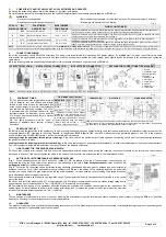
Hereunder the table of fluids compatibility and the min/MAX temperatures of the standard gaskets supplied by
FOX s.r.l
.
WARNING!
• Never try to repair gaskets
• Before disposing of gaskets, verify the leaking cause. Perhaps the problem is different.
• Replace gaskets after five operating years
• Elastomers are special non toxic littering.
Tab. 2
FOX s.r.l
SYMBOL
ISO
SYMBOL
ELASTOMER
DESCRIPTION
ELASTOMERS
TEMP. RANGE
FLUIDS COMPATIBILITY
-
NBR
Acrylonitrile, Butadiene
-40°C ÷ +120°C
Very good resistance to mineral and animal fats and oils, aliphatic hydrocarbons. Resistant to alkali. Not suitable for
use with amines, ketones, esters, benzene ethers, chloridated solvents and concentrated acids.
E
EPDM
Ethylene-Propylene Diene
-30°C ÷ +110°C
Very good resistance to heat, atmospheric agents; long life and good performance. Very good compatibility with acids,
alcohols, ketones and esters. Bad resistance to oils and fats.
T
PTFE
Polytetrafluorethylene (Teflon®)
-50°C ÷ +150°C
Very good resistance to heat and to almost any chemical aggression; not suitable for use with dichlorobenzene,
dietilamine, fluorite, gold cyanide, vaseline.
V
FPM
Fluorine elastomer (Viton®)
-20°C ÷ +140°C
Very good resistance to heat, oils and silicon-based fats, aliphatic and dying hydrocarbons, gasoline, diesel, vinegar,
phenol, chloride, nitric and sulfuric acids, cleaners, ethylene glycol, plating solutions.
NOTE:
Min and max limits of temperature are shown in Tab.1 as
min/MAX (°C) working temperature, TS
. The temperature supported by elastomer will always be equal or higher than the equipment
one. For detailed information on chemical compatibility between fluids and elastomers, write to Manufacturer,
FOX s.r.l.
communicating the exact symbol of the fluid in use and the working temperature.
4. CONNECTIONS
WIRING
4.1
All the connections satisfy DIN 43650 Directions. The wiring must be performed by clean hands (not grease stained), by qualified staff, in a clean room; after fixing, check
with a tester the signal quality; protect contacts with specific silicon based grease; tighten the screw; always leave slightly loosen the threads in the connector and tighten the
cable clamp.
4.2
In the following table are shown the detailed projects of two standard connections used commonly by
FOX s.r.l
.
Fig. 1
P2 ELECTRICAL CONN.
M2 ELECTRICAL CONNECTION
M3 ELECTRICAL CONNECTION
EXPLOSE FOR CONNECTIONS TYPE M2 AND M3
1 -Gasket
2 -Contacts hld grp.
2a-Contacts holder
2b-Contact
3 -Binding screw
4 -Protection
5 -Screw press
6 -Washer
7 -Cable clamp
8 -Fixing screw
NOTE:
Electrical protection according to DIN 40050 Directions - IP54 with protection cap for P2, IP65 for M2 and M3.
Fig. 2
5. EQUIPMENT
FIXING
5.1
The gasket seat (side implantation) must be
void of defaults: rust free surface and integral
thread. Apply some grease for elastomers and
screw the equipment in its place side installation
(see table aside, Tightening coupling). The use of
a dynamometric key becomes capital with less
resistant material, as aluminium, brass and AISI
316. Always use recommended tools to prevent
warrant exclusion.
5.2
The same procedure must be used in
presence of adaptors male-, female- or flange-
connected.
TIGHTENING COUPLING (Nm)
FEMALE CONN.
MALE CONN.
K7 AND K9 ADAPTER
FOX s.r.l.
can supply on demand many hydraulic adapters, even upon Customer’s project.
As these items may vary considerably, the matter won’t be discussed in this Handbook, but all details
are explained in the drawing that Manufacturer sends for approval.
MATERIALS
10x1
1/8”
1/4”
Steel
20 20 30
AISI
316
15 15 20
Brass 7.5
7.5
15
Aluminium 6.2
6.2
12.5
-
Tightening coupling values change
depending of the thread width, not on
thread type: the loading difference due
to thread type is meaningless, while it’s
relevant depending of the used material.
-Always take into account a ±10%
tolerance on the values shown.
6. PRESSURE
TEST
(PT)
6.1
Before joining the connection to the equipment, it’s highly recommended to produce an hydraulic test to verify that the equipment body is installed correctly on the plant. The
necessary pressure,
PT
, according to the ruling Directive, is calculated as
PT=PS (bar) x 1.43
, where PS means plant max. admissible pressure, and 1.43 is the minimum
coefficient shown by 2014/68/UE Directive. Two can be the fluid leaking reasons:
Leaking through the equipment thread (external leaking);
in this case, check if the equipment is correctly tightened, the bearing seat is free from manufacturing scraps and
the gasket is insert in its place.
Leaking through the diaphragm/piston (internal leaking);
in this case, contact as soon as possible the Manufacturer, to obtain the replacement of the product under warranty.
Don’t try to repair or manipulate the instrument, as this could cause the warranty withdrawal.
7.
LINK CONNECTOR - PRESSURE/VACUUM SWITCH
7.1
Check that contacts are clean and rust free: they must appear metal colored and polished; during the insertion, the connector should not be forced, and it should enter
thoroughly in its seat. At this moment tighten the screw in the center of the connector: the pressure switch is now installed and linked.
Fig. 3
8.
SETTING OF ELECTROMECHANICAL PRESSURE SWITCHES
Fig. I
When electrical connectors 16x16 and 30x30 (called M2, M3) are placed at the top of the equipment, the setting can be
performed removing the fixing screw of the connector, and introducing in the hole a
2mm hexagonal spanner
which will locate the
setting grub screw
put inside of the equipment.
Fig. II
For series K9, the setting can be performed turning clockwise the anodized aluminum gear to increase, and anti-clockwise to
decrease the value. For all other mechanical pressure switches by
FOX s.r.l.
, the setting of the operating point can be performed
working on a knob, a screw or a grub screw put on the top of the equipment.: turning clockwise, the pre-loading of the spring increases,
while it decreases when turning anti-clockwise.
Each mechanical pressure switch has its own regulation range. The equipment works at its best when the setting value is in the central
part of the range.
8.1
Check by a tester the signal quality. For a longer electrical life, it’s strongly recommended to supply a steady voltage rating and to
keep always an eye to the data shown in Tab. 1 (WORKING); it’s important to not exceed them.
8.2
Temperature and ageing of the equipment affect the intervention precision; this condition can compromise the repetition of the
settled signal. It’s recommended to perform a fine setting at full rating, and to replace the equipment when the intervention precision
exceeds the tolerance percentage shown in Tab. 1 (Working).
9. MAINTENANCE
There’s no need of maintenance. In case of shock or breaking, the Manufacturer supplies technical assistance and spare parts; contact in writing the
FOX s.r.l.
Post-Sale
Assistance. It’s strongly recommended to use only original spare parts.
10. GUARANTEE
The product is under warranty, provided that all preceding conditions are met. The Manufacturer cannot be held responsible for accidental damage to persons, animals or goods
caused by improper or irresponsible use of the equipment.
FOX s.r.l. via Romagna, 6 – 20090 Opera (MI) – Italy - tel. +39.02.57.60.00.33 - +39.02.57.60.65.43 – Fax +39.02.57.60.01.76
http://www.fox.it e-mail:fox@fox.it
Page 2 of 2
Fig. I
Fig. II


