background image

-2-

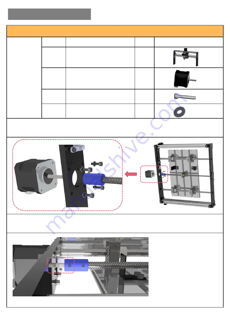
Part-2 Y-axis Stepper Motor Assembly

Required 

Parts

No.

Name

QTY

Picture

2.

Y-axis Base

1

3.

42 Stepper Motor

1

19.

M3*12 Bolt

4

22.

Φ3 Gasket

4

Step 1: 

Assemble the Y-axis stepper motor as following pictures. Fix the motor to the back of the base 

with M3*12 bolts and gaskets. 

Note: the wire port should face to the right.

Step 2: 

Connect the lead screw to the stepper motor with set screw. 

Note: fasten the set screw to the flat side of the motor shaft.

I. Hardware Assembly

Summary of Contents for 3018-SE

Page 1: ...CNC ROUTER 3018 SE USER MANUAL...

Page 2: ...bly 6 Part 7 Case Assembly Right Panel 7 Part 8 Emergency Stop Switch Assembly 8 Part 9 Door Handle Assembly 9 Part 10 Case Assembly Front Panel 10 Part 11 Cooling Fan Assembly 11 Part 12 Case Assembl...

Page 3: ...t 4 22 3 Gasket 4 Step 1 Assemble the X axis motor as following pictures Fix the motor to the left side of the frame with M3 12 bolts and gaskets Note the wire port should face backward Step 2 Connect...

Page 4: ...Gasket 4 Step 1 Assemble the Y axis stepper motor as following pictures Fix the motor to the back of the base with M3 12 bolts and gaskets Note the wire port should face to the right Step 2 Connect t...

Page 5: ...Part 3 Gantry Assembly Required Parts No Name QTY Picture 16 M5 14 Bolt 8 24 5 Gasket 8 Step 1 Fix the gantry right next to the pads on the base with M5 14 bolts and gaskets I Hardware Assembly 1 2 3...

Page 6: ...Parts No Name QTY Picture 4 Mainboard 1 Step 1 Assemble the mainboard to the back of the machine right next to the side panel First loosen the T nuts insert them to the aluminum profile and then tight...

Page 7: ...re 5 Left Acrylic Sheet 1 11 Pad 2 17 M5 30 Bolt 4 24 5 Gasket 4 25 TN5 6 20 Nut 4 Step 1 First connect the left acrylic sheet and pad together via M5 30 bolts Keep the nuts loose and put them into al...

Page 8: ...uction Block Assembly Required Parts No Name QTY Picture 14 Magnet Suction Bracket 1 19 M3 12 Bolt 2 22 3 Gasket 2 Step 1 Fix the magnet suction block to the left panel with M3 12 bolts and gaskets I...

Page 9: ...re 6 Right Acrylic Sheet 1 11 Pad 2 17 M5 30 Bolt 4 24 5 Gasket 4 25 TN5 6 20 Nut 4 Step 1 First connect the right acrylic sheet and pad together via M5 30 bolts Keep the nuts loose and put them into...

Page 10: ...Assembly Required Parts No Name QTY Picture 13 Emergency Stop Switch 1 18 M4 12 Bolt 4 Step 1 Put the emergency stop switch through the mounting plate Fix the mounting plate to the right panel with M...

Page 11: ...Handle 1 Step 1 Loosen the screws of the handle s fixing block remove the fixing block Put the door handle into the preserved hole on the acrylic sheet Fix the door handle to the acrylic sheet with f...

Page 12: ...se Assembly Front Panel Required Parts No Name QTY Picture 9 10 Front Acrylic Sheet Door Handle 1 20 M4 8 Flat Head Screw 4 Step 1 Fix the front side acrylic sheet to the hinges with M4 8 screws I Har...

Page 13: ...an Assembly Required Parts No Name QTY Picture 15 Cooling Fan 1 7 Back Acrylic Sheet 1 21 M4 8 Modified Truss Screw 4 Step 1 Use 4pcs M4 8 screws to fix the cooling fan to the back acrylic sheet I Har...

Page 14: ...omplete the wiring Shown as following picture connect the wires to the corresponding ports 12V Spindle 12V Laser X axis Y1 Z axis Y2 USB Port Offline Module 12V Fan Reset Z Zero Pause Continue Water C...

Page 15: ...13 Part 12 Case Assembly Back Panel Step 2 Fix the acrylic sheet with M5 30 bolts and gaskets Tighten the bolt through the pad to the base I Hardware Assembly 1 2...

Page 16: ...nnector Assembly Required Parts No Name QTY Picture 12 Corner Connector 2 18 M4 12 Bolt 4 23 4 Gasket 4 Step 1 Put the corner connector inside the case fix it with M4 12 bolts and gaskets from outside...

Page 17: ...ylic Sheet 1 12 Corner Connector 4 18 M4 12 Bolt 8 23 4 Gasket 8 Step 1 Fix the 4pcs corner connectors to the sides panels adjust their position to make sure they are leveled Step 2 Put the top panel...

Page 18: ...16 Part 14 Case Assembly Top Panel Assembly finished I Hardware Assembly...

Page 19: ...k Computer Select Manage Select Device Manager from left pane For Windows 10 Right click This PC Select Manage Select Device Manager from left pane In the tree expand Ports COM LPT your machine will b...

Page 20: ...connect USB Console window prints CTRL X Grbl 1 1f for help if the connection is successful Console window prints Serial port error 1 No such file or directory indicates that the connection is failed...

Page 21: ...alue 10 means moving distance is 10mm Feed value 500 means 500mm min Step 3 Spindle test Click the button to start the spindle and adjust the speed to test Step 4 Open G code file Step 5 Preview Code...

Page 22: ...roper gap between the bit and object s surface is that only an A4 paper can move through tightly Click Zero XY Zero Z as below picture shows to set zero Z probe will be introduced in Part 3 Step 7 Clo...

Page 23: ...ow to Use Z Probe Step 1 Measure the thickness of Z probe Step 2 Modify Z probe parameter Default value is Z15 change it to Z15 04 base of the parameter measured in step 1 Thickness 15 04mm II Softwar...

Page 24: ...p 3 First set the X Y axis zero point follow Part 2 Step 6 and then place the Z probe Step 4 Click Z probe button to start detecting Step 5 Z probe detection finished Remove Z probe click Send to star...

Page 25: ...rkmanship under normal use during the Warranty Period III This warranty covers the repair or replacement of the broken parts at our discretion If there is any difficulty during using feel free to cont...

Reviews: