background image

This manual is the intellectual property of Foxconn Inc. Although the
information in this manual may be changed or modified at any time,
Foxconn does not obligate itself to inform the user of these changes.

Statement:

All trademarks are the property of their respective owners.

User

s Manual V1.0  for 6100M2MA series motherboard.

Symbol description:

Version:

Trademark:

Note:

 refers to important information that can help you to use motherboard

 better.

Attention:

 indicates that it may damage hardware or cause data loss,

and tells you how to avoid such problems.

Warning: 

means that a potential risk of property damage or physical

injury exists.

More information:

If you want more information about our products, please visit the following

website:  http://www.foxconnchannel.com

PDF 

文件使用

 "pdfFactory" 

试用版本创建


www.fineprint.com.cn

Summary of Contents for 6100M2MA series

Page 1: ...Manual V1 0 for 6100M2MA series motherboard Symbol description Version Trademark Note refers to important information that can help you to use motherboard better Attention indicates that it may damag...

Page 2: ...cteristics of information technology equipment EN 61000 3 2 A14 2000 Electromagnetic compatibility EMC Part 3 Limits Section 2 Limits for harmonic current emissions equipment input current 16A per pha...

Page 3: ...cturer HON HAI PRECISION INDUSTRY COMPANY LTD Address 66 CHUNG SHAN RD TU CHENG INDUSTRIAL DISTRICT TAIPEI HSIEN TAIWAN R O C SupplementaryInformation This device complies with Part 15 of the FCC Rule...

Page 4: ...menu 26 Standard CMOS Features 28 Advanced BIOS Features 30 Advanced Chipset Features 33 Integrated Peripherals 35 Power Management Setup 40 PnP PCIConfigurations 42 PC Health Status 43 Frequency Volt...

Page 5: ...6 Driver CD Introduction Utility CD content 48 Start to install drivers 49 Directions for Bundled Software TigerONE 51 Fox LiveUpdate 57 Table of Contents 4 Chapter 5 Chapter...

Page 6: ...ure to switch off the DC power supply may result in serious damage to your system or memory module We cannot guarantee that your system will operate normally while over clocked Normal operation depend...

Page 7: ...gabit LAN 6 with 6 channel audio Default is elliptical 8 with 8 channel audio E with 1394 Connector S with SATA Connector R with RAID function 2 with DDR2 function You can find PPID label on the mothe...

Page 8: ...nce reliability and quality at a rea sonable price This motherboard adopts the advanced NVIDIA GeForceTM 6100 nForceTM 430 410 chipset providing us ers a computer platform with a high integration comp...

Page 9: ...emory l Supports 128 256 512 1024 Mb technology up to 4GB USB 2 0 Port l Supports hot plug l Eight USB 2 0 ports four rear panel ports two onboard USB headers providing four extra ports l Supports USB...

Page 10: ...8 optional l Supports Intel High Definition Audio l Supports S PDIF output l Supports high quality differential CD input l Supports 8 channel audio Onboard Graphics l Supports integrated VGA display...

Page 11: ...onsumption and power management features PCI Express x1 Support l Supports 250 MB sec 500 MB sec concurrent bandwidth l Low power consumption and power management features Advanced Features l PCI 2 3...

Page 12: ...12 Floppy Disk Connector 13 IrDA Connector 14 Clear CMOS Jumper 15 ATX Power Connector 16 DDR2 DIMM Slots 17 CPU Fan Connector 18 CPU Socket 19 NVIDIA GeForceTM 6100 20 System FAN Connector 21 12V AT...

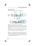
Page 13: ...Mouse Port PS 2KeyboardPort Parallel Port Printer Port LAN Port 4 VGA Port 3 1 2 5 6 7 Line in Line out 10 Microphone Rear LFE CEN Side 9 1394Port optional 8 Line in jack Line out jack Microphone jack...

Page 14: ...hard drive and floppy drive data cables and setting up various other feature of the motherboard Caution should be exercised during the installation process Please refer to the motherboard layout prio...

Page 15: ...such as an attached power supply before handling components to avoid damaging them due to static electricity 2 Unplug the power cord before opening your chassis or touching any components 3 Hold compo...

Page 16: ...e socket until it fits in place 3 When the CPU is in place press it firmly on the socket while you push down the socket lever to secure the CPU The lever clicks on the side tab to indicate that it is...

Page 17: ...ng from high speed operation for example overheating you need to install the proper fan The following procedure is provided for reference only please refer to your CPU fan user guide for the actual pr...

Page 18: ...tion mechanism to secure the heatsink and fan to module base 4 Align the other end of the reten tion bracket to fasten the cooling set on the top of the retention mechanism 3 Place the cooling set ont...

Page 19: ...12 Chapter 2 Installation Instructions 6 Connect the fan s power cable to the appropriate 3 pin terminal on the motherboard...

Page 20: ...ly 128 Pins 112Pins Installation of DDR2 Memory 1 There is only one gap in the center of the DIMM slot and the memory module can be fixed in one direction only 2 Align the memory module to the DIMM sl...

Page 21: ...ng table list is the recommended memory configurations Please in stall the memory according to the list Mode DIMMA0 DIMMB0 DIMMA1 DIMMB1 Populated Signal channel Populated Populated Populated Populate...

Page 22: ...he connector on the motherboard Firmly plug the power supply cable into the con nector and make sure it is secure ATX 12V Power Connector PWR2 The 4 pin ATX 12V power supply connects to PWR2 and provi...

Page 23: ...n connect the gray connector to the UltraDMA 133 100 66 33 slave device hard disk drive and the black connector to the UltraDMA 133 100 66 33 master device If you install two hard disks you must confi...

Page 24: ...tatus the LED is off Power Switch Connector PWRBTN Attach the connector to the power button of the case Pushing this switch allows the system to be turned on and off rather than using the power supply...

Page 25: ...ed ray The relevant parameters for the BIOS Integrated Periph erals should be set prior to using this function IR 5V GND IRRX IRTX Empty 1 10 9 Audio Connectors CD_IN AUX_IN optional CD_IN AUX_IN is S...

Page 26: ...vides two kinds of audio output choices the Front Audio the Rear Audio Front Audio supports re tasking function Their priority is the same For 8 models optional SENSE_SEND PORT1_L PORT1_R PORT2_L F_AU...

Page 27: ...r COM2 This motherboard provides an additional serial COM connector for your machine Connect one side of a switching cable to the connector then attach the serial COM device to the other side of the c...

Page 28: ...High Bandwidth per Pin Low overhead Low latency PCI Express supports a raw bit rate of 2 5 Gb s on the data pins This results in a real bandwidth per pair of 250 MB s A point to point connection allow...

Page 29: ...is unplugged Please read the docu mentation that came with it and make the necessary hardware settings for the card 2 Remove the bracket facing the slot that you intend to use Keep the screws for lat...

Page 30: ...r to the table while adjusting jumper settings Clear CMOS Jumper CLS_CMOS This motherboard uses the CMOS RAM to store all the set parameters The CMOS can be cleared by removing the CMOS jumper Referen...

Page 31: ...eeps or additional messages appear on the screen If you do not see anything within 30 seconds from the time you turned on the power the system may have failed a power on test Check the jumper settings...

Page 32: ...T process 2 You want to change the default CMOS settings This chapter includes the following information v Enter BIOS Setup v Main Menu v Standard CMOS Features v Advanced BIOS Features v Advanced Chi...

Page 33: ...ter SETUP ESC to enter Boot Menu Main Menu The main menu allows you to select from the list of setup functions and two exit choices Use the arrow keys to select among the items and press Enter to acce...

Page 34: ...ed through this menu PC Health Status This will display the current status of your PC Frequency Voltage Control Frequency and voltage settings can be adjusted throughthis menu Load Fail Safe Defaults...

Page 35: ...set up the desired time usually as the current time with hour minute second format IDE Channel 0 1 Master Slave These categories identify the HDD types of 2 IDE channels installed in the computer syst...

Page 36: ...ystem will stop and you will be prompted No Errors The system boot will not stop for any errors that may be detected All But Keyboard The system boot will not stop for a keyboard error but it will sto...

Page 37: ...select the priority for CD ROM startup After pressing Enter you can select the CD ROM using the PageUp PageDn or Up Down arrow keys and change the CD ROM priority using or To exit this option press Es...

Page 38: ...y Seek If this option is enabled BIOS will activate the floppy drive during the system boot and the drive s indicator will flash after the activation The magnetic head will move back and forth from A...

Page 39: ...used in NT4 0 OS vOS Select For DRAM 64MB This option is only required if you have installed more than 64 MB of memory and you are running the OS 2 operating system Otherwise leave this option at the...

Page 40: ...tter of K8 NB NB SB NB SB vK8 NB NB SB HT Width These options are used to set the bandwidth of the link s transmitter of K8 NB NB SB vErr94 Enh This option is used to set Err94 Enh vDRAM Configuration...

Page 41: ...ning vCKE base Power down mode This option is used to set the CKE base Power dowm mode vCKE based Power dowm Control This option controls the CKE based power down vMemory hole Remapping This item is u...

Page 42: ...to set whether the onboard FDC controller is enabled vOnboard Serial Port 1 2 This option is used to assign the I O address and interrupt request IRQ for the onboard serial port 1 2 Note Do not try to...

Page 43: ...The setting values include Disabled 378 IRQ7 278 IRQ5 and 3BC IRQ7 vParallel Port Mode Select an address and corresponding interrupt for the onboard parallel port The setting values include SPP EPP EC...

Page 44: ...aster access to IDE devices If you install a device that supports UItraDMA change the appropriate items on this list to Auto The available setting values are Disabled and Auto vIDE DMA transfer access...

Page 45: ...on is used to disable or enable the RAID function When enabled the following grayed items will be activated vSATA 1 2 Primary Secondary RAID These feature allow users to enable or disable the RAID fun...

Page 46: ...e Support This option is used to set whether the USB mouse controller is enabled in a legacy operating system such as DOS The available setting values are Disabled and Enabled vAC97 HD Audio This opti...

Page 47: ...wer will be cut off after a delay period The status of the computer before it enters STR will be saved in memory and the computer can quickly return to the previous status when the STR function wakes...

Page 48: ...m This function needs to be supported by the relevant hard ware and software vCase Open Warning This option is used to enable or disable case open warning function vPower On by Alarm This option is us...

Page 49: ...P then select Auto ESCD and the BIOS will automatically distribute interruption resources If the ISA cards you installed not support ing PnP you will need to select Manual and manually adjust interrup...

Page 50: ...to the computer vCPU Vcore 3 3V 5V 12V 5VSB Voltage Battery Current CPU Temperature Current SYS Temperature CPU Fan Speed System Fan Speed These items display the current status of all the monitored...

Page 51: ...rol vVDIMM Voltage Select This option is used to select the VDIMM voltage v1 2V Core Voltage Select This option is used to select the 1 2V Core voltage vVcore Voltage Select This option is used to sel...

Page 52: ...Set Supervisor User Password on the main menu and press Enter The following password dialog box appears Enter Password Enter your password not exceeding 8 characters then press Enter you will be promp...

Page 53: ...een Quit Without Saving Y N Press Y to discard any changes that you have made in the Setup Utility and exit the Setup Utility press N ESC to return to the main menu Under the menu Advanced BIOS Featur...

Page 54: ...came with the motherboard contains useful software and several utility drivers that enhance the mother board features This chapter includes the following information v Utility CD content v Installing...

Page 55: ...stall Driver Using this option to install all the drivers for your motherboard You should install the drivers sequentially from first to last A NVIDIA Chipset Driver B Realtek Audio Driver C NVIDIA VG...

Page 56: ...atic You can select the Utilities that you want to install and begin the setup steps There are two ways to install drivers manual or automatic Click the drivers that you want to install and begin the...

Page 57: ...Chapter 4 Driver CD Introduction 50 This chapter will introduce how to use attached software This chapter provides the following information v TIGER ONE v Fox LiveUpdate 5 5 Chapter...

Page 58: ...E you can Modify system performance settings such as bus speeds CPU voltages fan speed and other system performance options that are supported by the BIOS Monitor hardware temperature voltage frequenc...

Page 59: ...n to exit the program Minimum Click this button to minimize the window Configuration Click this button to configurate the parameters for the program It determines which items will be shown in shorten...

Page 60: ...ts you set memory and PCI Express frequency by manual Go to CPU page Select the different benchmarks Ajust by manual Apply the changes Close this page Reset the changes Go to Freq page Close this page...

Page 61: ...able alert function when the CPU temperature is higher than high limit value Show current high limit value of CPU temperature 4 2 Limit Setting Sys Temp This page lets you to set system high limit tem...

Page 62: ...Enable alert function when the CPU fan rev is lower than low limit rpm value Show current low limit rpm value of CPU fan 4 4 Limit Setting Sys Fan This page lets you to set system low limit rpm and en...

Page 63: ...Software 56 5 Fan Page Fan Control This page lets you enable smart Fan function or set fan speed by manual Go to Fan page Set fan speed by dragging the lever Enable or disable smart fan function Rese...

Page 64: ...e system BIOS drivers and utilities by local or online Supported Operating Systems Windows 2000 Windows XP 32 bit and 64 bit Windows 2003 32 bit and 64 bit Using Fox LiveUpdate 1 1 Local Update BIOS I...

Page 65: ...ame Click here 1 3 Local Update Update This page lets you update your system BIOS from Internet After click Update there will show warning message please read it carefully If you still want to continu...

Page 66: ...you update your system BIOS from Internet Click start it will search the new BIOS from Internet Then follow the wizard to finish the update operation Click here Current information Search new BIOS fr...

Page 67: ...r system drivers from Internet Click start it will search the new drivers from Internet Then follow the wizard to finish the update operation Click here Current information Search new drivers from Int...

Page 68: ...net Then follow the wizard to finish the update operation Click here Current information Search all new BIOS drivers utilities from Internet 2 3 Online Update Update Utility This page lets you update...

Page 69: ...art searching and related information will show on the task bar Click here Set auto search options Select search which kind of versions Apply the changes Reset to default value Note When enable auto s...

Page 70: ...ut Fox LiveUpdate 3 2 Configure System This page lets you set the backup BIOS location and change different skin of the utility Click here Set the location of download files or auto backup BIOS Determ...

Reviews: